Homeβ€Ί JGAurora A5S, A1 & A3S-V2β€Ί Getting Started & Troubleshooting

Killed it. Help :(

Richy_TRichy_T Posts: 142🌟 Super Member 🌟
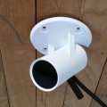
I had left some PLA in the printer for about a week while I wasn't using it and it had cracked in a few places. I was having trouble getting it out so I pulled the bowden tube out at both ends and was able to remove the filament easily enough. I had the printer running since I wanted the hot-end hot. As I was stuffing the bowden tube and wired back into the cable management, I heard a pop and now no more 3D printer :(Β 

I've tried turning it off for a while but no luck. The top fan on the hot-end comes on (which is always running I think) but nothing else. I have some rough ideas where to start looking but could really do with some help.

Thanks.

Comments

  • Richy_TRichy_T Posts: 142🌟 Super Member 🌟
    I do have one green light on the PCB and one on the power supply.
  • Richy_TRichy_T Posts: 142🌟 Super Member 🌟
    I've pulled the control board and can't see anything obviously wrong (no black marks or anything like that). I had the hot-end cooling at the time this happened so I don't think it was the heater that shorted out. But other than that, the fan and the thermistor don't seem like good candidates.
  • Richy_TRichy_T Posts: 142🌟 Super Member 🌟
    Poking around with my multimeter running just 24V, I'm not seeing many of the voltages I'd expect to see. I'm not sure if there should be 12V but there should definitely be 5V and there are a couple of 3.3V regulators on there. I'll need to get set up for some proper testing as hanging it out of the bottom of the printer is likely to be asking for trouble.

    Current thought is that it was the second fan and that I somehow grounded the wire. I'll definitely have to check that before everything goes back together. Especially if I end up buying another board.
  • Richy_TRichy_T Posts: 142🌟 Super Member 🌟
    I'm thinking I probably blew fuse F1. I see 4.6V one side and 1.2 the other. Does anyone know what spec this fuse is?
  • Richy_TRichy_T Posts: 142🌟 Super Member 🌟
    edited May 2020
    Correction, I think the fuse is fine. It's getting hot from high current and it appears to be a poly fuse so it's resetting to about 1 ohm when not powered. So probably a mosfet shorting out. Unfortunately, it isn't getting warm because the fuse is taking all the heat so I'm thinking I may need to put a little voltage on the other side of the fuse and see what gets hot. The fuse is 0.35A in case anyone needs to know.
    Post edited by Richy_T on
  • Samuel PinchesSamuel Pinches Posts: 2,997Administrator
    Hey @Richy_T - what a pickle! What model printer (and motherboard) are we talking about here? With mains unplugged, can you connect to printer from computer? Anything on LCD?
  • Richy_TRichy_T Posts: 142🌟 Super Member 🌟
    It's the A1. The board is this one:Β https://www.jgaurorastore.com/jgaurora-a5s-3d-printer-mother-board-main-controller-board-with-self-developed-firmware/

    The only way I'd be able to connect from a computer would be if the board was getting 5V from the USB port (which does happen). It's looking like a short which probably means a mosfet. I'll be doing more debugging in the next couple of days.
  • Richy_TRichy_T Posts: 142🌟 Super Member 🌟
    Well, I tried applying 5V directly to the 5V rail. The only things that got hot were the 3.3V regulator and the microcontroller.


  • Richy_TRichy_T Posts: 142🌟 Super Member 🌟
    Well, that's about the limit for me. I pulled the mosfets on the right of the board just because (it didn't help) but I think the CPU is basically fried. I ordered up a new board. I'm just hoping that whatever killed the old one doesn't kill the new one.
  • Samuel PinchesSamuel Pinches Posts: 2,997Administrator
    I'm sorry @Richy_T - maybe it is worth looking closely at the cable assembly to see what might possibly have made contact. If it was a 24V short and was loud enough, then surely there would be some spark residue somewhere that would give you confidence that you found the source of the problem.
  • Samuel PinchesSamuel Pinches Posts: 2,997Administrator
    Moved this thread to the A1 section.
  • Richy_TRichy_T Posts: 142🌟 Super Member 🌟
    Yeah, I'm going to have to tear down the hotend a bit and see if there's anything I can see. I'll also be checking for grounds and shorts. I guess I have a month to do it in. There are some sharp edges on the hot end so I'll probably put a bit of kapton around. I recall not being that impressed with the isolation of some of the wires so I'll definitely be bearing that in mind.

    It's hard to think it was the 24V being grounded because that side of things is fine. I replaced the 3.3V regulator so it's not that. When I stopped current-limiting the voltage (5V on the 5V rail), the buzzer started sounding.

    I'm wondering how viable replacing the STM would be. I know there is firmware available but is there some kind of bootloader on there? I'm assuming that it can't be simple. Not that I'm really in a hurry to solder that many pins by hand anyway...
  • Samuel PinchesSamuel Pinches Posts: 2,997Administrator
    Flashing the STM32 chip is not hard, soldering is the issue... and the potential for other issues to be the cause.
  • giantrobot2001giantrobot2001 Posts: 106🌟 Super Member 🌟
    Wow, sounds like something got burned.Β  Any idea what it was that made contact when you heard the pop? Kinda sounds like a loose connector threw a spark.
  • Richy_TRichy_T Posts: 142🌟 Super Member 🌟
    I'm not sure. I have the hot-end apart and there's nothing obvious. I was worried that I had pulled a wire tight on a rough edge on the heatsink but it's not really that rough. Obvious candidate is the heater but I can't see where that could have happened. Next is the thermistor. I'm not 100% happy with how that is held in the hot-end but it looks OK. Other than that, there's either of the fans or the x-stop.

    So not really sure. I'll try each of the connectors and make sure there's a resistance there and not a short to ground. Then when I get the new board, I'll plug in one connector at a time so if it does pop again, at least I should have some kind of a clue. I'll probably add a bit of kapton on the top rim where the wires come out just on the off-chance.

    There's always the small chance it was just an unlikely coincidence. I'm not really buying that though.
  • Richy_TRichy_T Posts: 142🌟 Super Member 🌟
    So the replacement board came in a few days ago and finally getting around to recommissioning things. Here's a report on what I've found so far.

    My immediate aim has been to ensure that whatever killed the old board does not kill the new so I have been going though the connections checking for continuity and that there were no unexpected groundings. Upon testing the hot-end thermistor, I found infinite resistance with no ground issues. Upon removing the thermistor, it was apparent that it had undergone total failure with the wires no longer connected and just some metal blobs at the end.

    This thermistor is one that I had to replace sometime last year. While trying to resolve some nozzle issues, the thermistor became damaged. I ordered an OEM replacement but was able to source some thermistors without the lead but with the same spec that arrived more quickly. I was able to use the old lead with a new thermistor and believed (and still do) that I had an item of similar quality to the original. However, it seems that while I was trying to fix my filament issues, some part of the thermistor came in contact with a grounded part, causing my problems and killing the board.

    My concern is that something like this could happen again. The hot end, as far as I'm aware, provides no insulation inside the thermistor hole so potentially a bit of movement could cause a repeat of the situation. I'll take a close look at the thermistor to try and be sure there is no exposed metal. It seems like some kind of insulation would be in order?
  • giantrobot2001giantrobot2001 Posts: 106🌟 Super Member 🌟
    edited July 2020
    Seems like this is really common, and it shouldn't be....
    I just screwed down a thermistor and that's when I decided to order some Kapton tape for the first time. Could overlap those little fragile rubbery sleeves.

    You might try to review this discussion about the new skr board that has addressed the issue.
    I think there is a good answer right there for adding some type of circuit "make a small circuit board and add it to any controller board between the thermistor leads and the controller board input plug"

    Edit:
    You did the post in that same thread where I think it is where I got the idea for the Kapton tape when I messed with it.
    I would not be able to construct that circuit for a tutorial project, but I would love it if there was one to follow.


    Post edited by giantrobot2001 on
  • Richy_TRichy_T Posts: 142🌟 Super Member 🌟
    I'm not sure how such a circuit would work but it would definitely be a good idea.
Sign In or Register to comment.