Please note: the forum is closed.
No new user registrations are accepted. For more info, please click here.
No new user registrations are accepted. For more info, please click here.
How the filament out sensor works
 AETEK
Posts: 106🌟 Super Member 🌟
AETEK
Posts: 106🌟 Super Member 🌟
Hi Guys,
I have just developed a hardware upgrade for the A5 and am in the test phase. In the process of development, I came across some unexpected problems with the MKS TFT28 filament out sensor. The problem was not my own hardware development, but the filament out sensor on the touch display mainboard. Already when my A5 was delivered a few weeks ago that did not work properly. After I replaced the tinkered plug with a more suitable plug, it worked. Well, I could not print a lot because of the development work at this time. However, there were now reports of print interruptions (pause), which are probably due to an incorrectly recognized filament out signal.
To my knowledge, I am the only hardware developer here.
JGAUROA seems to have changed something in the last 7 months. Samuel has an A5 from December 2017 with the filament out switch of the first generation. In this series, the connection to the MKS Touch Display must have looked something like this:

In this
case, it does not matter how the plug is plugged into the MKS TFT28
board, as long as you catch the two corresonding pins.
If I pull the filament out plug out of the MKS TFT28 board, then I can use the ohmmeter to measure a connection between the mainboard GND pin and the black cable of the filament out plug.
So there is an additional GND connection after the contact. This means that the GND connection for the function of the filament out sensor does not have to be present at the plug. This GND connection comes from another location.


Digital signals always need a defined level (here 0V = GND or 3.3V = High).
If you put the plug the other way around, then the signal can not become a level other than low. That means the filament never goes out for the A5. That does not come up so fast. A roll of filament keeps a certain amount of time. Once the end of the filament has been reached, the A5 will not notice and prints without filament.
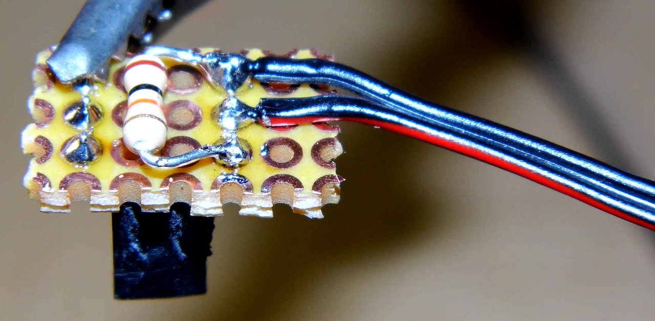
It is important to attach the additional 10 kOhm resistor directly to the connector.
Because the manufacturer's plug does not fit properly anyway, I built a better fitting plug from a female pin header and a piece of experimental PCB. There I have the space for the additional 10K pullup resistor.
How to build the plug with the 10k pullup resistor: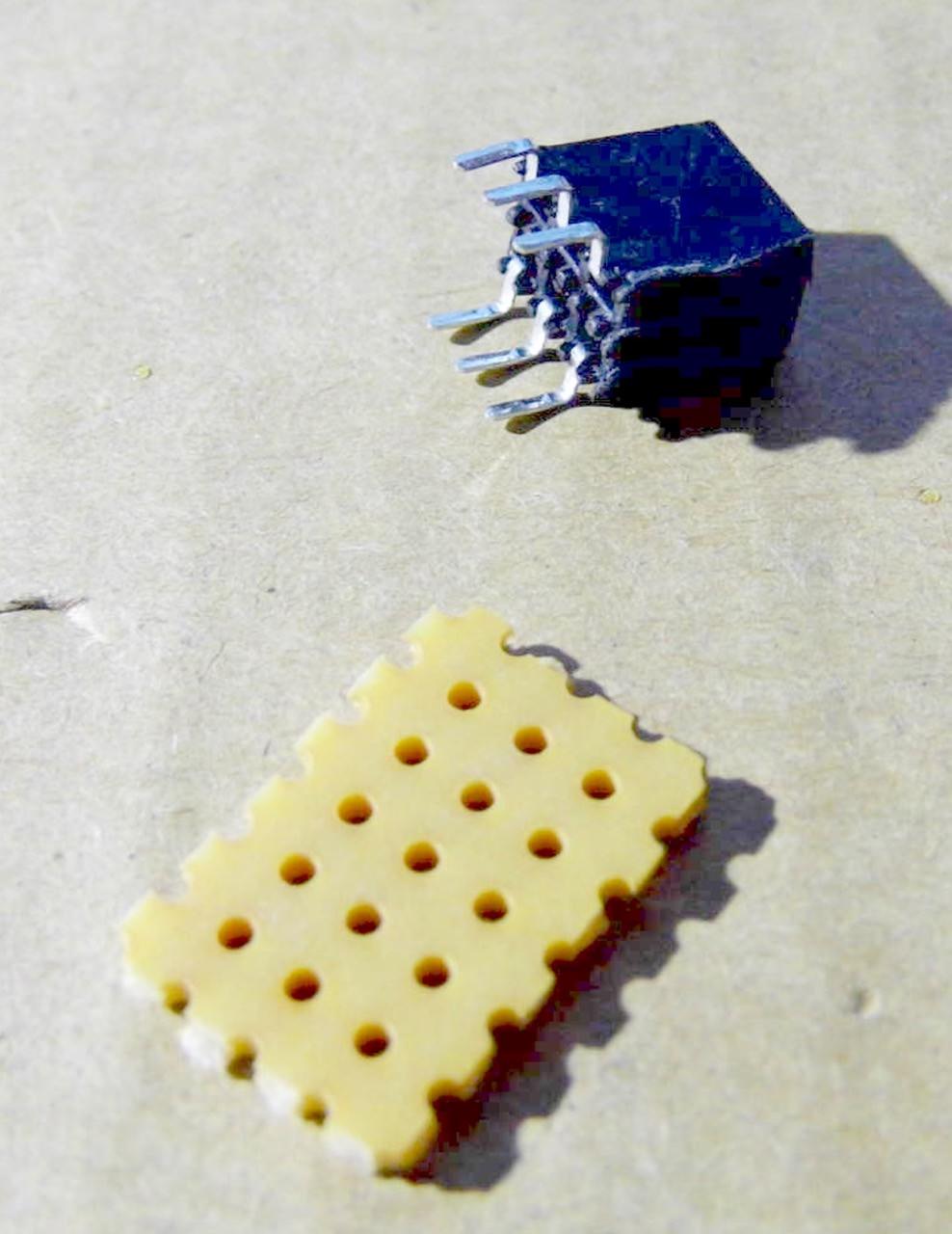


I have just developed a hardware upgrade for the A5 and am in the test phase. In the process of development, I came across some unexpected problems with the MKS TFT28 filament out sensor. The problem was not my own hardware development, but the filament out sensor on the touch display mainboard. Already when my A5 was delivered a few weeks ago that did not work properly. After I replaced the tinkered plug with a more suitable plug, it worked. Well, I could not print a lot because of the development work at this time. However, there were now reports of print interruptions (pause), which are probably due to an incorrectly recognized filament out signal.
To my knowledge, I am the only hardware developer here.
In order to be able to solve problems I had to analyze a part of the circuit of the MKS TFT28 mainboard with reverse ingeneering methods.
JGAUROA seems to have changed something in the last 7 months. Samuel has an A5 from December 2017 with the filament out switch of the first generation. In this series, the connection to the MKS Touch Display must have looked something like this:
This is different with my A5 (June-July 2018). Here it is important how you put the plug around.
I will explain how to check this with a multimeter.
If I pull the filament out plug out of the MKS TFT28 board, then I can use the ohmmeter to measure a connection between the mainboard GND pin and the black cable of the filament out plug.
That would not be so if the filament out switch was a normal, floating contact.
So there is an additional GND connection after the contact. This means that the GND connection for the function of the filament out sensor does not have to be present at the plug. This GND connection comes from another location.
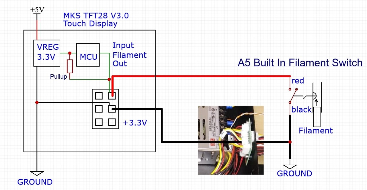
The Filament Out signal is routed inward along with other signals from the outside via the center connector. There is a PCB, which distributes the signals further. There is a connection to GND for the filament-out signal on this PCB.
The MKS TFT28 display uses a 32Bit MCU with 3.3Volt. On the MKS PCB is a voltage regulator, which generates the 3.3Volt from the 5Volt.
A pull-up
resistor ensures that with the filament out switch open (no filament
present) there is a high signal of 3.3 volts at the filament sensor
input of the MCU.
Digital signals always need a defined level (here 0V = GND or 3.3V = High).
If the switch is closed by the presence of filament, then the signal is set to GND (LOW).
If you put the plug the other way around, then the signal can not become a level other than low. That means the filament never goes out for the A5. That does not come up so fast. A roll of filament keeps a certain amount of time. Once the end of the filament has been reached, the A5 will not notice and prints without filament.
Now I have
explained why it is relevant with the currently existing circuit, in
which direction the Filament Out plug is plugged into the motherboard.
If the plug is then pointed up correctly, then the filament out detection does not work always and reliably. So far no circuit diagram has been published for the MKS TFT28 mainboard. Based on my experience, I know that relatively long cables to signal inputs can cause problems. In this case, I mean the distance from the MKS TFT28 motherboard to the filament out switch. Shielded cables can be used to protect the signal input from interference. This is just a simple high / low digital signal. Such an application is about clearly transmitting one of the two states. After
intensive research, I have found that the signal quality can be
significantly improved by an additional pull-up resistor, directly on
the plug.
Fortunately, the unused pin of the input carries the required 3.3 volts.
It is important to attach the additional 10 kOhm resistor directly to the connector.
Because the manufacturer's plug does not fit properly anyway, I built a better fitting plug from a female pin header and a piece of experimental PCB. There I have the space for the additional 10K pullup resistor.
PS:
Samuel, you may want to add this information to the WIKI
cheers
AETEK
Comments
In fact, this is an electronic problem. MKS may have changed the input circuit of the MKS TFT28 board over time. JGAURORA buys the boards and trusts in the correct function.
It is about the signal quality and the signal to noise ratio.
The additional 10k pullup resistor makes the signal clearer to the MCU. I could also imagine that MKS expected the connection of 3 pins (SIGNAL IN, GND and 3.3V). In this case, the pullup resistor would not be necessary. To save costs may JGAURORA omit the 3.3V line, because it works (mostly) without. I decided to solve my problem this way for two reasons.
There is only need for action if the filament out sensor is unreliable.
1. Filament shortage is recognized (PAUSE), even though filament is present.
2. Filament shortage is not recognized and the A5 does not PAUSE when the filament is over.
If not ask please what is still unclear.
Cheers
AETEK
I was wondering if perhaps there is noise on the ground line that is causing these faults. Perhaps a capacitor over the switch could help to eliminate noise and spikes.
I have not investigated if the original pullup is installed inside the MCU or separately. Yes, if MKS had installed a pull up resistor with a smaller value then it would work better.
Unfortunately, it is becoming increasingly common for products to be put on the market without beta tests. Customers involuntarily take on the role of beta testers. The problem will not be addressed until the vulnerabilities have been discovered.
This is a phenomenon with which we have to live in this price range.
My printer is brand new too when I found the problem. And the filament is perfectly fine, in fact if you hit resume, it will continue to print.
And the way they glue the connector is quite solid and the connection should be fine.
I think the way AETEK fixed it should be the answer. Although, @AETEK
Maybe you could find an easier solution? Without Soldering and using an resistor? How about we introduce a 3.3v line in the connector? Is it going to help?
Ok, but please allow me to explore this from another angel. Can we fix it with Marin firmware?
In Configuration.h we can see this
specifically, what do those parameters mean?
FIL_RUNOUT_INVERTING this means that it will use lo voltage as true instead of hi?
ENDSTOPPULLUP_FIL_RUNOUT this means that we can let Marlin to know if we have internal pullup?
FILAMENT_RUNOUT_SCRIPT this is useless it just mean we will use M600 gcode command when filament runout happens.
For me still is not clear one moment:
I have a problem with sporadic interruption of printing due too filament sensor. Supplier give fe advice to completelly disconnect B1 from TFT board. After that problem not occured again.
The question is: The B1 contacts in short circuit when filament is present. When B1 disonnectet from TFT board, pins on board are not connected to each other. but printer is working, so TFT board "thinking" that filament is present.
How?
My JG Aurora A5 was bought Oct 2018.
After several prints and approx 1.5 kg of filament I had problems with interruptions of prints, beeping and finally my A5 was not able to print as there were no files found on the USB. That led me to Da Hai's video and I tried to reverse the filament sensor plug as instructed. While removing unfortunately I destroyed the mks tft board as glue was not removed completely and so I pulled off the board pin connector including parts of board solder. No chance to repair.
I ordered a new board of which I received version 4.0 instead of 3.0. This was installed and printing is fine without the filament sensor plugged in. Unfortunately this function is lost at the moment.
If I connect filament sensor in any af the directions I receive the message "filament detection sensor is no pressed" when I start printing, independent of filament in or out.
Only exception: if plug put in original orientation (red wire in upper and black in middle) and no filament loaded, there is no message and printer would start.
Has anybody made similar experience? Any idea what will help. Would AETEK proposal help?
Is there any experience with the version 4.0 tft board? This has little different layout and I am not sure whether I have problem with my sensor or wiring or whether the board needs different wiring.
Thanks for your ideas
Krenex
Howdy, Stranger!
RegisterIt looks like you've been lurking for a while.
If you register, we will remember what you have read and notify you about new comments. You will also be able to participate in discussions.
So if you'd like to get involved, register for an account, it'll only take you a minute!