Home JGAurora A5 & A3S Modifications & Upgrades

Important things to know regarding stepper upgrade with TMC 2130 with SPI

Enrique RiriEnrique Riri Posts: 37🌟 Super Member 🌟
edited September 2018 in Modifications & Upgrades
Hi,
Had a lot of troubles upgrading to TMC 2130 v 1.1 using SPI, and after some hours, reads, tests, here are the MAJOR things to take care to success 100% this upgrade:

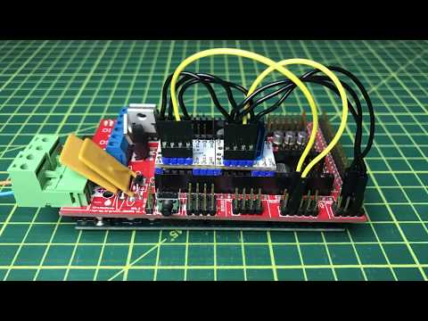
1st : Disconnect the 3 jumpers originally plugged on the Mother board , Under original steppers. Other way, you will blow the TMC2130 immediately and never see, you just burn your stepper board. Take care on that, happened to me.

2nd: Use only and exclusively Arduino v 1.8.5. Other way is hazardous and request some teawks . Follow the excellent videos in 2 parts provided.

3rd :Don't forget to erase internal RAM of motherboard after flashing: M502, then M500 with pronterface.

4th:  Execute the commands codes commented (like on the video) using pronterface to check all is fine. Take care here, my first try with blowed steppers (after my error not unplug the 3 jumpers), reports me all is fine, and allow me to adjust the tension correctly). So enven blowed, all seemed to be fine, but NOT : no X/Y mouvement.

5th: adjust the right voltage for each stepper.

6th: you need a cooler fan for the stepper Inside. This is mandatory.

Finally, you just need to use 2 steppers for X/Y motors, that's it; Z/E0 is a waste of money and not really relevant.

All these conclude my success upgrade with TMC 2130 SPI installation : 100% working.

Now, I'm totally conscient jumping to new firmware with the last release of Arduino will request new detailled topic to make. 

For thoses who want to go further and play with sensorless function:

Post edited by Enrique Riri on

Comments

  • Samuel PinchesSamuel Pinches Posts: 2,997Administrator
    Thanks for the valuable post Enrique - I will have to add these tips to the wiki!

  • Andrei ShekhauAndrei Shekhau Posts: 4Member
    Hello Enrique,

    if i forget to run m502/m500 commands after upgrade, the drivers fill be fried, or there is a chance that they will survive? This happened to me.

    The commands should be executed in pronterface or it is fine to do that in arduino ide through the teminal?

    Don't you think the upgrade of extruder and z axis may be useful to get the sensor-less mode working for them. This mode detects the load of the motor and sends 'no go' signal in case of an obstacle. This way the z motor will (theoretically) never be able collapse and scratch the heat bed in case it is incorrectly leveled. For extruder it may help preventing the filament grinding. Right now when the filament is loaded, once it reaches the hot-end the extruder motor still tries to bush it forward for some time, which results in filament grinding. Or even worth thing, when you press change filament on the screen, and instead pulling it out first you pulls it in, the extruder starts to push the filament as a crazy into hot-end. This could be avoided (again theoretically) by this motor load detection that provide those tmc2130 drivers. I understand, it would be better to modify a software to disable pulling in the filament option, before you pull it out, but this is how unfortunately it was designed in the software by Chinese producer. 
    Again, this is a theory, i have never tried it. I would like to know your opinion or may be somebody else has already experience with sensor-less mode.

    Thanks

    Andrei
  • Enrique RiriEnrique Riri Posts: 37🌟 Super Member 🌟
    edited October 2018
    Personnally, not yet tested SPI without endstops (seems in theory to work, but request candidates to validate). My thoughts and reads brings me the idea, it can be usefull for X/Y sensors axes, but not for Z.  Again not yet tested. Probably on my third printer who is somewhere travelling with GEARBEST. I will do that for test purposes only. What I'vez done on my 2 Jgaurora : 2x TMC2130 for X/Y + 2xTMC2208 for Z/Ext0. But results for Z/Ext is the same with standard drivers or 2208. More soon.

    Thanked by 1Andrei Shekhau
    Post edited by Enrique Riri on
  • netzmarknetzmark Posts: 107🌟 Super Member 🌟
    Hello Everybody on the group, this is my first post here :-).

    I have JGaurora on the way to me, expect to get it in 3-4 days, and without touching it yet consider the modifications :-).
    Driver as the first to change.

    Regardless we speak about 2130 or 2208 if it is bus interface wired - how we should to adjust the currents with the potentiometers if it is also adjusted by software? Understand potentiometer is over the software, it means it is just like hardware general limiter that cannot to be overed by software settings. So if we'll set with pots 700mA then can't set by soft 800mA, isn't it?. So in practice what the current (or voltages) should be set to be safe for steppers/drivers and to let flex adjusting by the software?

    Second question is: JGaurora has max speed 100mm/s (datasheet). So what is the sense to set hybrid threshold over that the mode will be changed from stealthchop to spreadcycle as 100ms. It will be never reached and machine will always work in stealthchop mode - is it just the idea to keep it always in this mode?

    brgds
    Marek


  • Samuel PinchesSamuel Pinches Posts: 2,997Administrator
    edited October 2018
    Welcome @netzmark :smile:
     
    My 2 cents: the speed limiting factor will likely be the extruder - the long bowden tube will limit your print speed to ~60mm/s.
    Post edited by Samuel Pinches on
  • netzmarknetzmark Posts: 107🌟 Super Member 🌟
    Hi Samuel
    yes, if it is also worth to replace E driver at all - oppinions about it seems be different in the net.
    But specialy in this case setting the threshold to 100ms seems be totaly senseless so...
  • coldpeetcoldpeet Posts: 3Member
    edited November 2018
    Hi everyone!
    I'm joining the topic. A few days ago I recived a package from aliexpress containing TMC2130 stepper drivers. I'm very eager to get to work and after abuot two days of fighting it looks like everything is working as it should. When I finally assembled the printer's housing, I checked the leveling of the heated bed again and started the first printout of the test cube 20x20x20mm.
    Of course, the printout fails because there is a shift od subsequent printing layers in the Y axis. I used the 2130 stepper drivers for the X and Y axes only. I set the voltage at the TMC 2130 to ~1.0V.
    Does anyone have any idea to solve this issue? What is going on? What did I do wrong or what I forgot? What's next?
    So many questions, no one idea. :smile:

    Edit: I forgot to say about some important matters. I read the forum here where AETEK gave voltage Vref for the X axis - 0.85V and for the Y axis = 1.25V. With this setting for the Y axis during heated bed movement and reaching the maximum position, a horrible sound appears and the motor is still trying to rotate. Decreasing the voltage Vref to the level of 1.1V doesn't change anything. Only values around of 1.0V give the proper work of the Y axis.

    Post edited by coldpeet on
  • Samuel PinchesSamuel Pinches Posts: 2,997Administrator
     Hi and welcome. Do you have a fan cooling the stepper drivers?
    Thanked by 1coldpeet
  • coldpeetcoldpeet Posts: 3Member
    Unfortunately I don't have a fan. Only standard heat sinks. Today it is almost midnight, so I'm going to sleep. Tomorrow I will try to assemble something and cool these stepper drivers.
    I focused so much on the changes in the Marlin software, and I forgot about such a mundane matter.
    I will describe the results of my struggles here - Unless it is spamming the forum.

    By the way, I'll ask if after installing the active cooling should I use the suggested voltages Vref (X axis = 0.85V and Y axis = 1.25V)?
  • Enrique RiriEnrique Riri Posts: 37🌟 Super Member 🌟
    edited November 2018
    Hi, sounds maybe you have a wiring issue with one of your drivers. First step: mandatory to place a fan directed to heat sinks.
    Have you keep off all the jumpers under the TMCs?

    The fact you hear horrible noise from one motor, is a sign of Under/over power the stepper motor.
    Check again all from scratch step by step. No Reason not to work.
    Finnally: have a spare TMC if you have a doubt: Simply to exchange.
     
    Post edited by Enrique Riri on
  • coldpeetcoldpeet Posts: 3Member
    Hi Enrique!
    I've checked the wiring several times, I'm sure it's okay. In fact, initially the CS pin in the X axis wasn't good, but I corrected it. Jumpers under the X and Y axis controllers are removed.
    Of course I have spare drivers (3 pieces).
    Today I'll continue to work on this topic (my wife isn't happy).
    If I manage to get through all these difficulties, I'll try to reasonably describe the reasons for these errors and the solution.
  • Enrique RiriEnrique Riri Posts: 37🌟 Super Member 🌟
    Did you solve your issue ?
  • itou31itou31 Posts: 3Member
    Hi,
    I'm thinking to update to TMC2130 to reduce noise on X/Y and also in E as I'm often printing voronoi, and the retractation make some noise.
    After viewing DaHai youtube part1 and 2, I decided to order TMC2130 V1.1 (not arrived yet). I even read the wiki (https://jgaurorawiki.com/a5/silent-stepper-driver-tmc2130).
    But after digging into TMC drivers, when navigating in wiki, I can't find this page, and found the one with TMC2208.
    So I don't know what to choose. As the TMC2208 seem to be more plug and play, should I order the TMC2208 ?

    Either with 2130 or 2208 dirvers, The printer should be powered ON (because af 24V for Vref), but do I need to unplug the motors ?

    In the Wiki, Red_M state to use the firmware 1.1.9C beta. But is it possible to use the 1.1.8C ?

    Thanks
  • Der_MuckDer_Muck Posts: 265🌟 Super Member 🌟
    Ahm ok you allready ordered the 2130 so stay with them. All you need to do is set Vref on each TMC right, connect the wires right and deside if you want SPI. You also need to active cool them, there are some cooling ducts who direct the air directly to the TMCs. Just print them first!
    For all that you can stay with the 1.1.8C its no problem at all, I also have that this way. 
    Just go the way in Dahais Video and it should work right.   
    In the end you should know how to use a multimeter and little elektronic knowlage. 
  • klreeseklreese Posts: 5Member
    Unfortunately, after installing TMC2130 drivers for X and Y, wiring for SPI mode, and modifying the firmware, I got no response from the X and Y axis steppers. I KNEW I had forgotten something. I came here and found this thread. Thank you. Of course . . . I forgot to remove the jumpers. I pulled the jumpers and tried again, but same result.

    So there was no evidence of burning; no sound, no smell. The TMC2130 boards look fine. Is there a way for me to test the driver boards? Or is that a waste of time and I absolutely killed them?

    Thank you!
    Kevin
  • Der_MuckDer_Muck Posts: 265🌟 Super Member 🌟
    Did you reset the eeprom?
    Again, these are Mods that take much care, please check everything 1000 times before powering.
    Best is to set a step by step plan to double check everything. Most important is the correct wireing!
  • klreeseklreese Posts: 5Member
    Thank you, Der_Muck. I hadn't reset the eeprom. Still no luck, but at least I have more information.

    I re-uploaded the firmware again, plugged the LCD cable back in, sent M502, then M500. Both were acknowledged with a response. But still no movement in X and Y. Wires have been double-checked. All jumpers in the X and Y driver sockets are pulled. Also, even though current control will be handled by the Arduino, I set the X Vref to ~0.85 V and the Y Vref to ~1.25 V.

    With the Serial Monitor open in the Arduino software, I plugged the mainboard USB to my computer without powering up the A5 and I got output from the unit that seemed normal. Last output of the startup sequence was the initial setting of the X and Y current starting levels. It'll stay like that if I do nothing else. But as soon as I power on the unit, I get the error "X driver overtemperature warning". This happens immediately and I've repeated this several times.

    Is this the kind of thing that might happen with a damaged TMC2130? I have replacements, but wasn't wanting to snip off the pins if I might use them for another project. What's weird is that the Y axis reports no such error, but also fails to move. Meanwhile the Z axis still reponds to commands.
  • klreeseklreese Posts: 5Member
    Hmmmmm. I replaced the X axis TMC2130 with a new one. Vref set to ~0.85 V. Same result exactly. As soon as the main power switch is turned on: "X driver overtemperature warning"

    To be thorough, I will replace the Y axis driver later this evening. Three of the pins are wired together on the two drivers, so perhaps a bad Y driver could show up in an X axis error.
  • klreeseklreese Posts: 5Member
    edited February 2019
    New TMC2130 drivers installed now for both X and Y axes. Wiring for SPI mode (not using sensorless homing) has been quadruple checked. Still, as soon as the primary power switch is turned on, the "X driver overtemperature warning" error is sent.

    These are the Fysetc 1.0 boards with the SPI bridge jumper removed for SPI mode. Now I'm realizing that a lot of the information that I found online was for using the v1.1 boards. Do I need to reconfigure the drivers with the small jumper/bridge pads? Perhaps the default configuration is different?

    Post edited by klreese on
  • Der_MuckDer_Muck Posts: 265🌟 Super Member 🌟
    In a upgrate to the TMCs there is nothing more to do than in Dahais Video is showed. Double check the wireing thats a bit tricky maybe the cables of the motor have a problem.
  • itou31itou31 Posts: 3Member
    Hi there,
    Finally, I go with the TMC2208 UART mode following dahai video 3. The TMC2130 V1.1 are still not arrived. I got the TMC2208 before.
    I have changed the X, Y and E drivers. Let all current anf threshold by default.
    All works good in silent, the E sound a little bit while retracting but less than before.
    All I can hear are the fans now.
  • klreeseklreese Posts: 5Member
    edited February 2019
    So, I haven't been able to work on this since my last post, but on my lunch break at work I just discovered what I *hope* will be the only problem. I also hope that this will help someone avoid the trap I fell into (or maybe I'm just confused about something).
    When installing the TMC2130 chips into the A5, I used Google images on my phone to find the wiring diagram for convenience. I pulled up a diagram that I was sure was the right one . .  .looked just like the one from Da Hai's video. Well it wasn't. The cable select lines are terminated on different pins. So the first chance I get to correct that, I will try it out and hopefully my printer will be back in operation.
    Turns out the image I was using came from this page:
    That diagram has CS X going to pin D59 and CS Y going to D63. Here's what's weird . . .
    On that same page, they show making the following firmware tweaks (just like Da Hai's tweaks):

    #define X_STEP_PIN         54
    #define X_DIR_PIN          55
    #define X_ENABLE_PIN       38
    #ifndef X_CS_PIN
      #define X_CS_PIN         64 // default 53
    #endif
    
    #define Y_STEP_PIN         60
    #define Y_DIR_PIN          61
    #define Y_ENABLE_PIN       56
    #ifndef Y_CS_PIN
      #define Y_CS_PIN         44 // default 49
    #endif

    That page needs to be corrected or else I'm just missing something. Those cable select pins for X and Y axes stepper drivers don't match the wiring diagram on the same page.


    Post edited by klreese on
  • Der_MuckDer_Muck Posts: 265🌟 Super Member 🌟
    As I remember, I did it like Dahai in his Video and I had no problems.

    The text seems to be written before he changed the wires so it worked for him.
    Thanked by 1Samuel Pinches
  • Samuel PinchesSamuel Pinches Posts: 2,997Administrator
    edited February 2019
    It was written by someone who I don't think is a member on the forum - unfortunately, I don't have time to try to figure it all out and fix it.

    If anyone wants to have a go at a new guide based on DaHai's instructions, it would be very welcomed. I'm happy to help if you have formatting problems.

    I think it would be good to start a new page, because that one was specifically for people using the 1.1.9 beta, which I still don't recommend.

    Post edited by Samuel Pinches on
  • sasasasa Posts: 36🌟 Super Member 🌟
    Folks,
    found this wiring diagram for stepper upgrade (it is from board vendor on Aliexpress , recommended by Enrique. Vendor ships fast, quality is good). It is quite different from the one in Wiki, and from Da Hai video. Can it be trusted?

  • Samuel PinchesSamuel Pinches Posts: 2,997Administrator
    I don't think it matters which wiring you use - its just a matter of telling the firmware which pins to expect communications on. I can't see of any advantage to either of the options.
Sign In or Register to comment.