Please note: the forum is closed.
No new user registrations are accepted. For more info, please click here.
No new user registrations are accepted. For more info, please click here.
Why do the thermistor inputs break sometimes?
Hello,


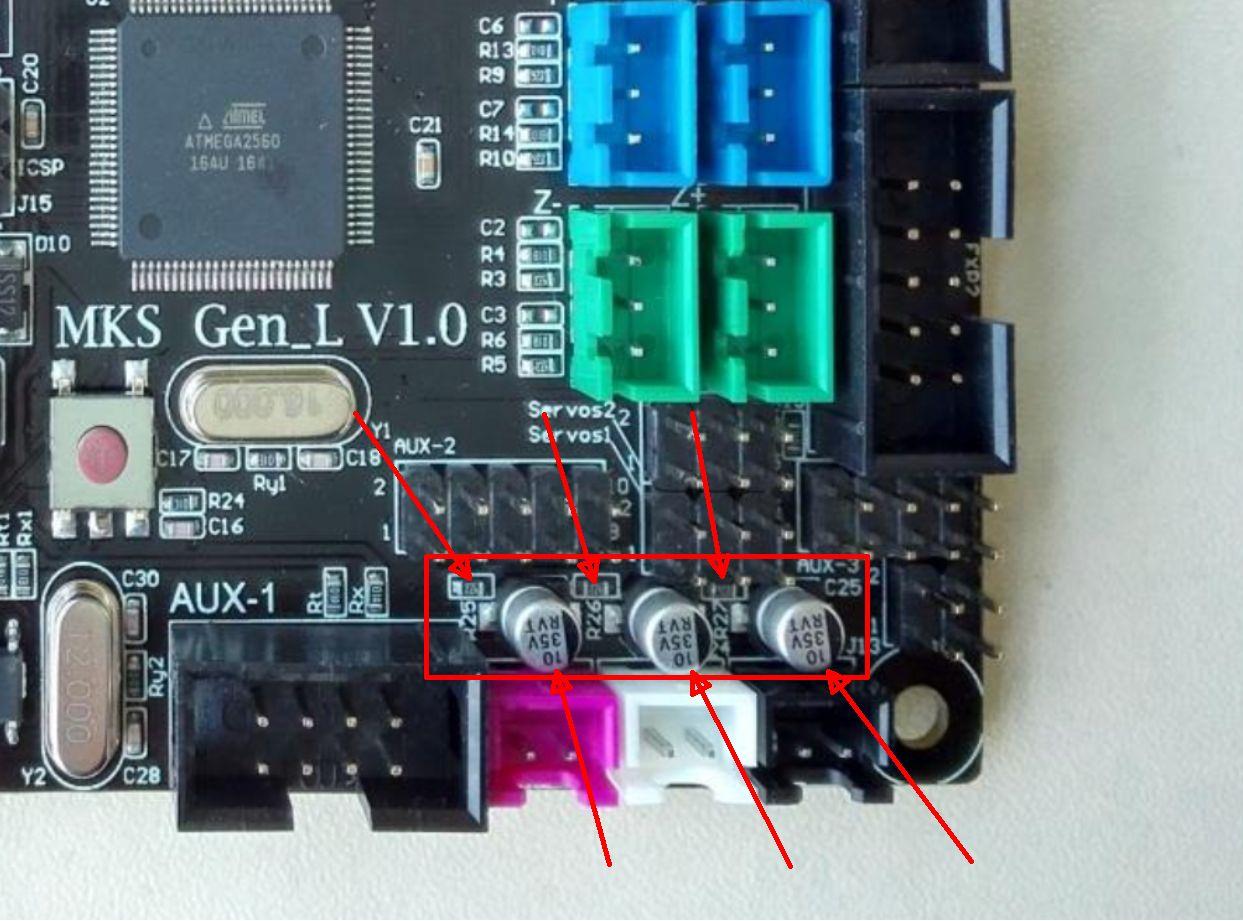
I have heard several times that the MKS GEN-L mainboard has problems with the inputs of the temperature sensors in combination with the A5. I am developing circuits myself around the AVR microcontrollers and I am interested in what the cause of the problems is. The MKS board is RAMPS 1.4 compatible. This means that the Ramps 1.4 circuit diagram is largely consistent with the MKS Board. If you look at the wiring of the temperature sensor inputs, then you realize that there are only two components per input. One part is a resistor that forms a voltage divider in combination with the thermistor. The second component is an electrolytic capacitor, which is used to filter interference signals. This corresponds to a low frequency filter. The input resistors on the MKS board (R25 ... R27) have a value of 4700 ohms. Due
to a short circuit of the thermistor, the resistors can not burn
because the maximum possible current through the resistor is limited to
1.06mA @ 5V DC.
A defective electrolytic capacitor can corrupt the measured value. Therefore
I would first connect a normal 100k ohm resistor to the input to be
tested and then solder out the corresponding 10uF capacitor. If the measured value then shows approx. 20C, the capacitor is defective and should be replaced.
The analog inputs of the microcontroller can handle both + 5Volt VCC and ground (0V) potential without harming it. It has also been heard that on the case of the A5 under certain circumstances + 24V DC may be present. If the 24V gets in contact with any of the Thermistor (Analog ADC) inputs, then the AVR Controller (MEGA2560) will be damaged. It does contain internal clamping diodes; but these are not designed for such a burden. Maybe we should secure the thermistor inputs externally. There are clamp circuits or in the simplest case a 5.1V Zener diode and a resistor for current limiting.
The analog inputs of the microcontroller can handle both + 5Volt VCC and ground (0V) potential without harming it. It has also been heard that on the case of the A5 under certain circumstances + 24V DC may be present. If the 24V gets in contact with any of the Thermistor (Analog ADC) inputs, then the AVR Controller (MEGA2560) will be damaged. It does contain internal clamping diodes; but these are not designed for such a burden. Maybe we should secure the thermistor inputs externally. There are clamp circuits or in the simplest case a 5.1V Zener diode and a resistor for current limiting.
It
would be interesting for me to find out if users who have problems with
the thermistor inputs also have problems with the 24V DC on the chasis.


Thanked by 1Samuel Pinches
Post edited by AETEK on
Comments
I had to open my A5 again, because my motherboard fan is mounted too high and the Y-axis can not drive the whole distance.
On this occasion, I then carried out measurements.
I looked at the Arduino 2560 referencing circuit.
Stray voltage in my opinion can cause no defects in the ADC (thermistor) inputs. More likely is the destruction of the Mega 2560 microcontroller and the CH340 USB chip. This is what other users have already reported.
The topic Stray Voltage should be considered separately.
For me, only one possibility comes into consideration.
What is your mains voltage?
Regarding the stray voltage:
My mains is 240V (+/-10V). The stray voltage is common to many devices with ungrounded metal chassis - the y-class filter capacitor in a switch mode power supply can pass AC voltage at very low current, there are many reports of this in metal MacBooks if you search "macbook tingling". I worry that this could pass via ground USB into the motherboard, and then cause damage by reverse polarity or voltage damage.
However, I have not yet seen any users with a damaged Mega2560 or CH340? Have you heard of some?
GND is the DC potential (galvanically isolated from the mains).
Earth is zero potential (N)
Strictly speaking, the A5 switching power supply is capable of this (galvanic isolation). I have already analyzed the A5 power supply and found about 4 capacitors connected between ground (green / yellow) and neutral (blue). Here in Germany you can plug the power plug in two directions into the wall socket. Then you suddenly have a stray voltage between live wire (brown) and earth on the capacitors in the switching power supply. If the Chasis of the A5 is grounded, then this voltage is due to Chasis. If you now connect another grounded device, such. PC via USB then a current can flow over the ground contact, which can damage equipment. I know that's all pretty hard to understand. We've also written about this topic before. Well, to avoid the problem (Stray Voltage) I have earthed my A5 power supply, but mounted on isolation blocks. So that no stray voltage from the grid via earth can get into the printer. So almost made of the internal power supply an external power supply, which allows galvanic isolation.
a) Use an USB isolator (always!)
b) Use an isolating transformer.
c) For a notebook, only use the power supply via the battery (not mains) when connecting to A5
d) Add a WiFi connection to the 3D printer (on my ToDo list). This is not recommended for firmware updates.
Howdy, Stranger!
RegisterIt looks like you've been lurking for a while.
If you register, we will remember what you have read and notify you about new comments. You will also be able to participate in discussions.
So if you'd like to get involved, register for an account, it'll only take you a minute!