Please note: the forum is closed.
No new user registrations are accepted. For more info, please click here.
No new user registrations are accepted. For more info, please click here.
Warning: Heated Bed Power Clamps
 AETEK
Posts: 106🌟 Super Member 🌟
AETEK
Posts: 106🌟 Super Member 🌟
Hello,
After the work I wanted to test the function of the A5. For this I printed a small object (shopping cart coin dummy) and tried on this occasion also new start GCODE. This time I did not print the object as usual in the middle of the print bed, but in front of the edge.
After the Nozzle Priming Line, the nozzle touched the front left metal retaining clip.
At that moment, I could see a clearly perceptible spark. This has nothing to do with stray voltage. I have installed my isolators and the A5 has printed from the SD card, no USB connected. Fortunately, nothing bad has happened yet.
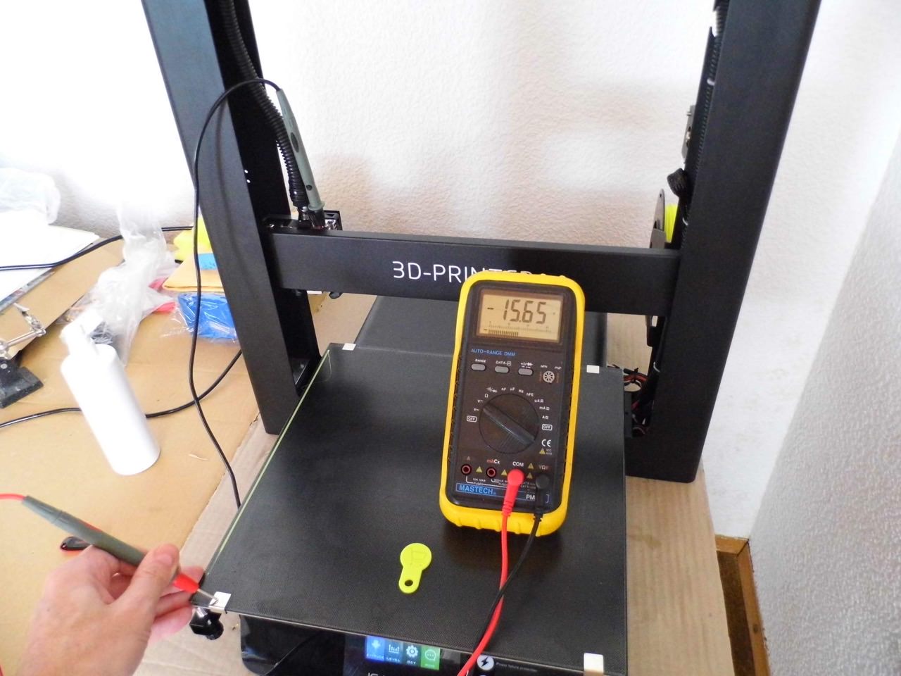
Now I wanted to know how something like that can be. During printing, I measured at the cold end and the bed's retaining clips. I noticed an applied voltage of more than 16 Volts. The strong spark, which was previously created, indicates that a strong current must have flowed. After
the end of printing, I repeated the measurement and in fact the voltage
of 16.56 volts is still applied to 3 of 4 retaining clips.
I recently checked the wiring of the Hotend Thermistor and the Hotend Heater Cartridge when it received the printer. There was no reason to complain. According to my current knowledge, the problem is the retaining clips, which are very tight.
The underside of the heated bed contains the PCB tracks supplied with 24 volts. Due to the flow of current, the heated bed gets warm. These tracks are insulated by a protective paint.
It will probably be the case that the paint was scraped off by the clamp when attaching the retaining clips. Then the retaining clip is connected to the circuit of the heating bed!
This is a time bomb for the electronics of the printer. The only remedy is to remove the clips or to insulate them proper.
But then this must be a stable and heat-resistant insulation. Maybe Capton tape? I do not have that here. Normal plastic insulating tape can melt in the heat 
I want to say this warning first, before others are less fortunate and then the electronics are broken.
With this "improvement" JGAURORA has installed another source of error.
Too bad that I have to make such warnings.
Greetings from Germany
AETEK
Greetings from Germany
AETEK


Post edited by AETEK on
Comments
that might be the reason for the blue tape glued onto the heatbed (below the clips) when the A5 was shipped. I removed the blue tape, as I considered it as being some transport protection.
Will verify if I have that issue as well and insulate the bottom side with either Kapton tape or maybe insulation pads like for mounting TO-220 cases
Regards
Andreas
I have found remnants of 0.5mm printed circuit board copper coated.
Then I etched the copper away and mounted the PCB material down between the clamp and the heated bed. This is glass fiber reinforced plastic, which withstands temperatures of over 200 ° C during soldering and is also very robust mechanically. After the installation, I measured again with the multimeter and now everything is ok. I also adjusted my start G code so that the nozzle no longer hits the clamp.
At delivery I had no blue tape at the bottom of the clamps.
That could actually be considered a transport protection.
Voy a tener en cuenta vuestras experiencias en mi A5
Gracias por vuestras soluciones.
Luis
Hello from Melbourne!
Howdy, Stranger!
RegisterIt looks like you've been lurking for a while.
If you register, we will remember what you have read and notify you about new comments. You will also be able to participate in discussions.
So if you'd like to get involved, register for an account, it'll only take you a minute!