Homeโ€บ JGAurora A5 & A3Sโ€บ Getting Started & Troubleshooting

Inconsistent layer stacking

GandyGandy Posts: 89๐ŸŒŸ Super Member ๐ŸŒŸ
Prints come out more or less good on my A5, but there is a problem with the layer stacking I cannot get rid of. Being irregular, I cannot quite attribute it to z-axis wobbling, at least as a single cause:

The effect is visible on the 3D-Benchy I printed for reference (Cura 4.0.0, 0.2mm, 10% infill, 100%fan with BlowHard3000; see attached cura-settings.txt).ย  I'm using Marlin bugfix-1.1.x with S-Curve-Acceleration, Linear Advance and Junction-Deviation (though the layer stacking loocked the same with both the stock FW and Marlin 1.1.8 w/out the extra features):
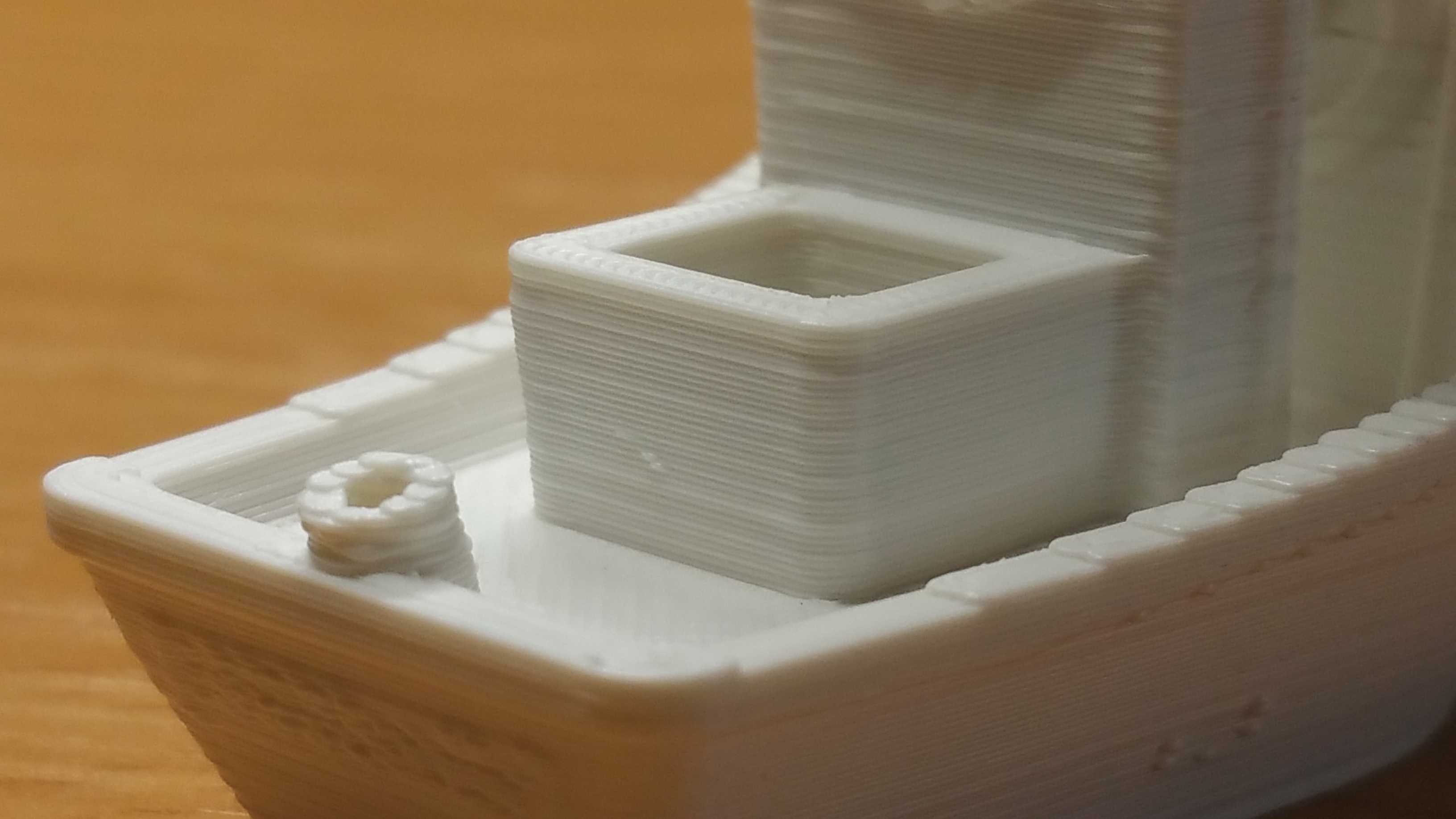
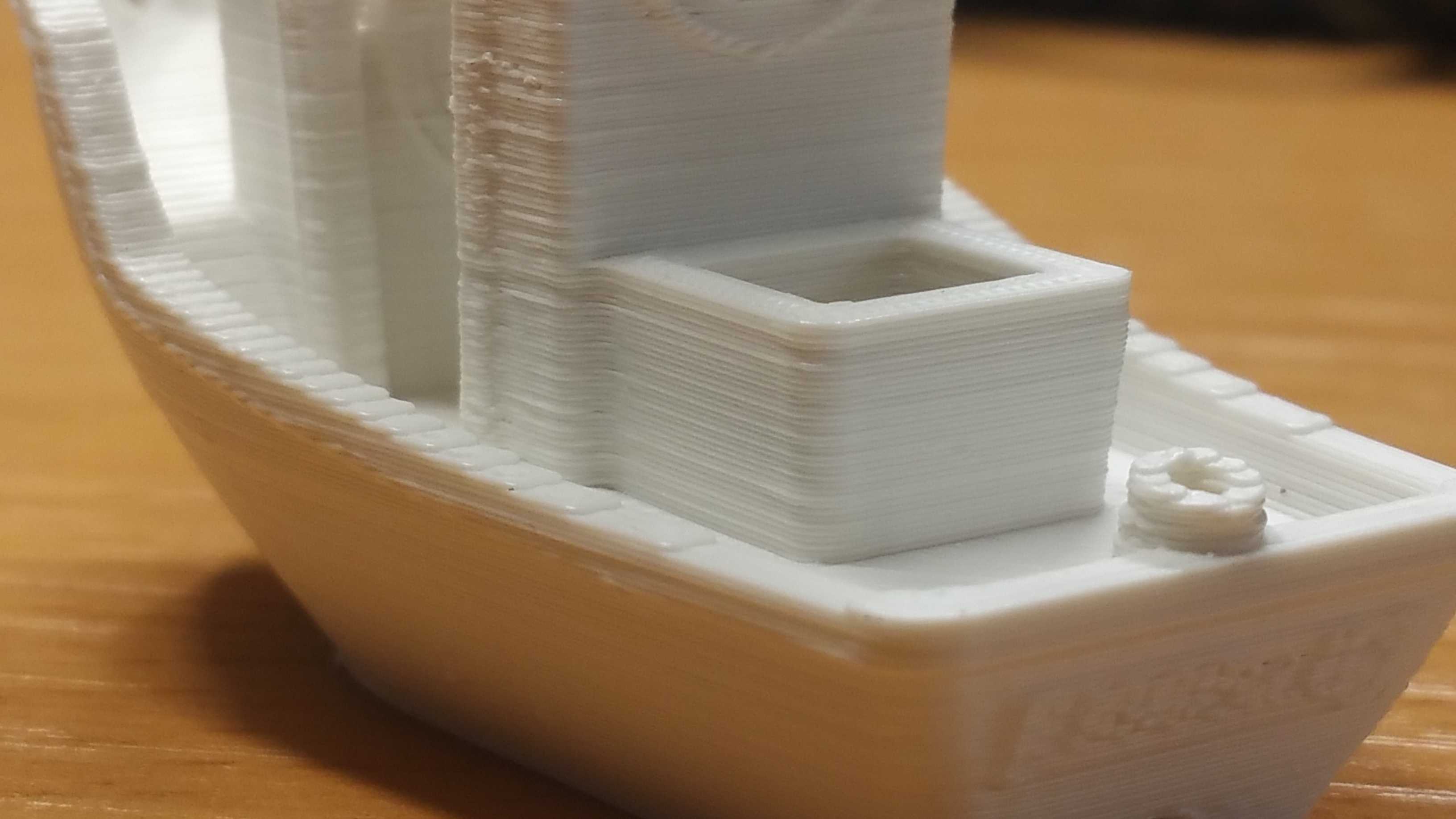
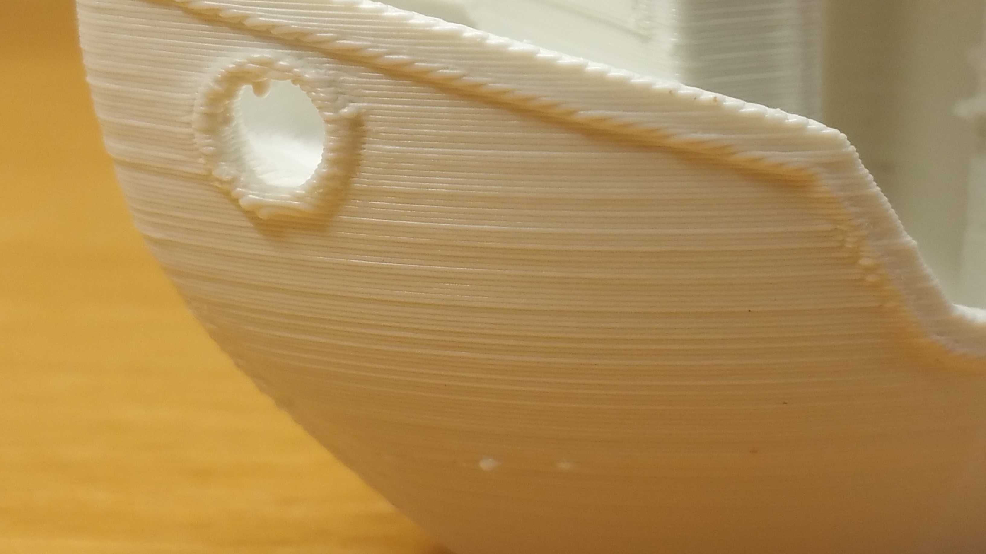
The filament I'm using is extrudr PLA NX2 with consistent diameter. I noticed however, that the extruder wheel imprints itself quite noticibly onto the filament, transforming it from O-shape to D-shape. The more ridig e-sun filament shipped with the printer didn't show this effect as much, but the layer consistency wasn't better, either. I did pay extra attention to extruder calibration.

Over the last few months, I've applied a few mods to my printer to aim for better mechanical stability:
  • Removed the spool holder from the chassis to keep the spool from picking up oscillations from the x-axis movement and feeding it back to the z-gantry.
  • Placed the whole printer on simple vibration dampers.
  • Replaced the bed springs with fixed nylon spacers (with internal threading to have a snug fit on the bed screws), using a BL-Touch for leveling.
While the first two helped with ghosting, the latter showed no obvious effects, neither for better nor worse. Unfortunately I only started printing 3D-Benchies after all those mods, so I have no objects that can be compared 1:1.

Since I installed TMC2208 I could hear the slightest grinding noise during movements but moving both the bed and the x-sledge by hand appears to be smooth enough. Nevertheless, I've just odered the set of higher quality bearings from AliExpress. Replacing the bearings will be a good opportunity to check the lead screws and the couplers.

Any suggestion on what else I could do to improve layer consistency is highly appreciated. Or is the quality visible on my 3D-Benchy already the best I could expect? What is the quality I can reach with the A5, can someone please post reference fotos?

Cheers,
Andy.
ยซ1

Comments

  • Samuel PinchesSamuel Pinches Posts: 2,997Administrator
    I would suggest to check all the screws to ensure everything is tight - especially the main 4 screws that hold the upright section.
    Thanked by 1Gandy
  • GandyGandy Posts: 89๐ŸŒŸ Super Member ๐ŸŒŸ
    Thank you for the suggestion, I just checked those 4 screws and all others accessible from the outside, but each and every screw was tight. Next time I open up the base I'll also check if the Y-gantry is fixed tightly to the base cover. I tried to carefully test for play but found nothing too obvious. I do have the impression the X-belt might be a bit loose though, how tight should that one be anyway? With the X-carriage at 0, I can bring the upper and lower section of the belt together with mild pressure up until about 2 cm shy of the far side.

    Do you have any other ideas what I can check?
  • WerewolfWerewolf Posts: 27Member
    Did you install anti Z-wobble flanges?
  • GandyGandy Posts: 89๐ŸŒŸ Super Member ๐ŸŒŸ
    edited June 2019
    Do you mean the additional contraints at the top of the lead screws like this one or that one? I didn't try this, yet.
    Actually, I've seen various posts reasoning that the additional contraint even makes things worse by making an already bent lead screw exert more force on the Z screws, displacing the setup in X- and Y- direction even further. They suggest to rather check the spacing between motor axis and lead screw within the coupler (they shall not touch) and to replace or straighten a bent lead screw. What are your experiences, do these flanges improve your prints? Which particular model can you recommend?
    Post edited by Gandy on
  • itisnot_meitisnot_me Posts: 102๐ŸŒŸ Super Member ๐ŸŒŸ
    The only thing you can possibly do to help is actually calibrate the extruder steps. Assuming you have at least 1.1.8 community firmware installed.

    I decided to actually do it I noticed my average extruded was 105.6mm instead of 100. To do this pull out the bowden from the hot end, use flush cutters to snip filament at end of tube. Extrude 100mm snip flush and repeat a min of 2 more times.

    Measure and get average of your 3+ lengths. And do some math and edit firmware.

    Math
    Get average (in my case 105.6)
    Get current firmware steps (typically 100)
    Firmware steps x 100 = 10000
    10000 / average (105.6) = 94.69

    Change your firmware steps to be the number you got in my case 94.69. upload firmware and test/repeat until happy.

    Once you are done calibrating make sure the tube fits all the way down again.

    ---

    Second thing is cura has layer widths at .4 instead of always suggested .5. change those. Then once you do that take a calibration cube, 0 top/bottom layers 1 wall (at layer width, if above it will be .5). Print that and measure the wall width. If it's at .5 perfect. If it's not the look up how to adjust the flow/extrusion multiplier. Since mine was good I didn't need to adjust.

    ---

    Make sure you also do a pid test on your hotend. Since you will be in the firmware it's easy to do it now.

    ---

    Lastly calibration cube x/y esteps. There are lots of Tut's on how to do this. Not as complicated as the first thing but still do it


    Once you do all of this and you want some help on a cura profile I do have a jgaurora A5 Reddit post with a profile there. It's not updated with my newest settings but I suggest changing layer width to .5
    Thanked by 1Gandy
  • GandyGandy Posts: 89๐ŸŒŸ Super Member ๐ŸŒŸ
    I've got the latest Marlin bugfix-1.1.x running on the machine for some time now. UBL together with BL-Touch and a fixed bed improved a lot for me.

    For each filament (actually, I used 3 so far, two of them being different colors of the same kind), I calibrate the extruder steps, do a temperature tower and figure out the K-factor for linear advance. Since the X-, Y- and Z-steps/unit are given by the mechanical design, I stuck to the presets. I'll add PID autotuning for the target temperature to that list.

    Your suggestion on the PID tuning got me thinking: Yesterday I printed a 60x60x20 mmยณ cube with one outer wall, no infill, no top or bottom layers and 0.5mm line thickness. It showed the same inconsitent layers as any other print. Due to the fact that there was only one wall line however, I got the chance to look at the inconsistencies differently: Everywhere I spotted a pronouced recess in the outer face of the wall, the same recess occured on the inside, pointing towards inconsistent extrusion rather than layer shifting. Lines, that would start out flush with the lines above and below would recede or bulge out at the end.

    So I shoved a cross-section of the print unter the microscope:

    Then I tried to overlay the individual layers with rounded rectangles of the same height (copied and centered at the right for reference):

    The left column shows all the regtangles aligned to the left; the widths of the rectangles vary by +/- 7% of the medium width.ย  While some of the rectangles might be slightly off-center in the horizontal direction, the dominating effect is a variation in layer width, aka extruded material. During the print, the hotend temperature varied within +/- 0.6ยฐC around 210ยฐC with a period of 15 sec to 25 sec. The feedrate was 15mm/s, so one side of the cube took 4 sec. That's roughly 1/4 of that period.

    I will do a PID autotune tonight followed by the same print to see if there are any improvements, but my feeling is that the +/- 0.6ยฐ can not completely explain the variation in cross-section, although there might be a correlation there. Maybe the long bowden tube has a few places with increased friction, where pressure in the filament piles up during times of low hotend temperature and releases when the hotend heats up again, amplifying the effect. I'll take a closer look at the bowden to see if it is bent somewhere.

    Thoughts, ideas and suggestions highly welcome.
    Thanked by 1Samuel Pinches
  • GandyGandy Posts: 89๐ŸŒŸ Super Member ๐ŸŒŸ
    @itisnot_me please share the link to your cura profile - I've printed a few filled blocks with layer width 0.5 earlier and encountered massive problems of the first of the top layers connecting to the wall. The second top layer was better but only the third was fully closed. Never seen that with 0.4, so I've probably missed something important, there.
  • GandyGandy Posts: 89๐ŸŒŸ Super Member ๐ŸŒŸ
    edited June 2019

    Post edited by Gandy on
  • GandyGandy Posts: 89๐ŸŒŸ Super Member ๐ŸŒŸ
    edited June 2019

    Post edited by Gandy on
  • GandyGandy Posts: 89๐ŸŒŸ Super Member ๐ŸŒŸ
    Minor update: The PID autotune yielded values quite different to the firmware default:
    • M301 P35.30 I4.35 D71.57  ; Firmware default
    • M301 P63.63 I7.13 D142.03 ; with fan off
    • M301 P67.55 I7.50 D152.17 ; with fan @ 100%
    The result however was similar: Temperature variations of +/- 0.4ยฐC, same surface finish as before.

    Searching on friction in bowden tubes I found an article obviously advertising some improved PTFE tubing and a FAQ in the JGAurora forum, recommending to lubricate the filament with a small amount of canola oil (thanks @Samuel Pinches).

    Checking the PTFE tube, I found no sharp bends, but the tube bend radius just before enering the print appears to be around 10cm (with 15cm recommended as a lower limit in said article). I'll try to straighten that out a bit and use canona oil for lubrication to see if this improves the prints. Can anyone recommend on the right amount of oil or how to do this exactly so I don't ruin my printer?

  • Der_MuckDer_Muck Posts: 265๐ŸŒŸ Super Member ๐ŸŒŸ
    PID tuning has always be done without the fan on, keep that in mind.ย  Yes, the default PID setting is far from reality, everyone should do a PID tuning on a new printer.

    The oil can be add on the filament, the filament transferes that oil in the hotend. I had very good results with DRY Lube PTFE spray directly in the throat. It leaves no oil which can set itself up on the nozzle. Max temp should be around 280ยฐC PTFE oil has a max temp of 250ยฐC and canona oil I realy dont know but it is for sure lower.
    Mostly it helps alot with PLA problems on all metal throats, it helps a bit on PTFE throats.

    Check your couplers on Z if they are centrical, @itisnot_me for example had very bad once, it can affect the layers in the lower part of the print because you get iregular preasure on the linear guides.

    I recommend the BGM extruder to improve the print quality a lot. Not important if it is the original or the clone. But with a other motor than the standard one. (BGM needs 3 times higher speed), the standard motor gets hot quick and skips steps it was very hard to finde out that the motor skips steps on the extruder.

    By the way, your print looks for me overextruded. Try to lower the multiplyer and start your testprints maybe near underextruding (0.95 in S3D I dont know how its in cura) and set it up after and after.ย  ย In S3D I end up using the automode for layer wdth because the fix set up end up sometimes in seperate outer and inner walls at thin walls.

    100% fan is not always a solution, I tryed it out on a good print setting which effect it has and found out that to much fan is contra productive. To less fan is not so bad than to much fan. But that ofcause is also different with differend build in fans, which makes help on costume systems quite hard. Every printer reacts differend, depending what tuning it has. But one is sure, the standard cause of problems doesnt fit to a tuned printer and the problems are mostly caused on wrong slicer settings. That I always found out. My problems where caused always on that and I always ment it where the hardware. (saves a lot of time with problem solving) Better to reset to default and beginn setting up a setting from beginning. One wrong setting and 1000 other settings which correct it can end in a good result but in the end it effects the print with a other model you want to print.ย  Default setup and little changes end up much better. (was also a long time for me to find out.)ย 

    Hope it helps you. Dont change to much in the firmware, always save your last firmware settings to be able to go back!
    And if its to late, better go back to default and change not to much at once. One change, one test and so on.
    Thanked by 1Gandy
  • GandyGandy Posts: 89๐ŸŒŸ Super Member ๐ŸŒŸ
    @Der_Muck, thank you for your insights and suggestions. I've printed another of those single wall boxes after lubricating the bowden, but it will not be before Monday that I can do another cross section. However, I will print a few of those boxes with different extrusion factors for comparison.ย 

  • Der_MuckDer_Muck Posts: 265๐ŸŒŸ Super Member ๐ŸŒŸ
    Yeah as I said, I also has a couple of problems, ment it was the filament but it was my fault because of a wrong setting. Now I always begin to search for the problem I may have in my slicer settings or firmware changes. Its easy and mostly the right corner to find and solve the problem.
  • itisnot_meitisnot_me Posts: 102๐ŸŒŸ Super Member ๐ŸŒŸ
    @Gandy I am very sorry but I was never notified you tagged me I have since subscribed to this thread.

    Firstly here is the most updated profile I use. It has been tested on other printers with success. I have tuned in the supports and tree supports along with a bunch of other settings.ย  (if you do not have 2208 drivers then up your retraction)ย https://mega.nz/#!HHxX2ACZ!SYBKPyJluKJrJT-mklifGhVE8dY1MUxO9Fa8q6uU9Qo

    So I went down the road more on this wobble issue and I found a very real problem. My coupler's were not concentric. I have since bought new ones and printed more tests to get to this.
    ย 


    The only difference in the above was new couplers. Same exact gcode.ย  I still have bent rods but it still is way better.

    You see how bad the one coupler is. Even worse is that they did not even provide the screws in the back holes to tighten onto the rod and shaft. This just shows poor caring about the printer.

    ย The I changed the nozzle and got this.


    As you can see it got slightly better. I still might change the rods in the future but the prints are much better.

    Thanked by 2Samuel Pinches Gandy
  • GandyGandy Posts: 89๐ŸŒŸ Super Member ๐ŸŒŸ
    @itisnot_me: First of all, thank you for the cura profile, I can't wait to take a closer look. You imply the retraction is different depending on whether I use TMC2208 (which I do) or not, can you elaborate on that?
    Regarding your couplers, I struggle finding words for that. It is hard to imagine how this could happen during transport, so apparently someone in production was having a really bad day... Good you found that and thank you for sharing, I will add it to the list of things to check on my printer. Where did you order the replacements?
    As reported, the cross-section of an earlier print showed clear signs of extrusion irregularities rather than z-wobble as the main cause for my layer inconsistencies. So I went ahead and tried to improve my bowden system:
    • I dismantled the bowden tube and checked for bents. As mentioned before, the area immediately above the print head was bent at a few places with radii <10cm, and looking at photos I have from unboxing the printer, this must have been there from the start. After unsuccessfully trying to bend the tube back, I cut it by 17 cm and mounted the extruder motor close to the top of the chassis - with a slight tilt for the bowden to better align with the flexible pipe:
    • After reconnecting the tube to the hotend, I dipped the end of the filament in canona oil, got rid of excess and inserted it into the bowden tube all the way to the hotend. For good measure (too good, actually, as I later learned), I repeated that two more times. Here, I noticed that quite close to the end, there is something causing increased friction on the filament. I suspect either the bowden coupler reducing the tube diameter (unlikely) or a slight step where the bodwen tube touches the heatbreak. I failed to inspect it more closely right there and then, so I will have to get back to this soonish.
    • I had to pump ~2m of filament through the hotend to get a properly closed outer wall again, with the first prints leaving oily residues on the print bed, so I obvisously exaggerated the oiling part. Apart from that, the extrusion quality did not improve noticably.
    Then I came up with another idea: I was thinking about how to best test if the extruder gear might play a role in the inconsistent extrusions. If that was the case, the extrustion variations should repeat with every full turn of the extruder gear, provided there are no skipped steps and the gear does not slip on the motor axis. So I scaled up my single-walled box to ~242x242 mmยฒ and tuned the extrusion factor so that each layer receives the exact amount of filament the extruder gear pushes forward with one full turn: The motor has 200 steps/turn, or 3200 steps at 16ยตstep-resolution and the extruder is calibrated to 100steps/mm, yielding 32mm per full turn. A 0.2mmx0.4mm extruded line is ~30 times that long, i.e.960 mm. The extrusion factor was then fine-tuned according to the cura output. This way, at any given point on the box's wall, the points above and below correspond to the same extruder gear position.
    For comparison, I made cross-sections of the 60x60x20 cube and the 242x242x20 cube (0.2mm x 0.4mm, no retracts):
    The four cross-sections on the left are made from the 60x60x20 box (not aligned with the extruder gear), the four on the right from the 242x242x20 box (aligned with the extruder gear). It is quite obvious, that the variations in wall thickness are much more prominent in the four cross-sections on the left compared to those on the right. Also, the visual impression of the surface is much smoother on the 242x242x20 box. I take this as a strong indication of the extruder gear being strongly involved in the inconsistent extrusion. So the next question I have to face is what is going wrong with the gear.
    I'm looking forward to your opinions and suggestions, especially how to trouble-shoot the extruder gear.
    Thanked by 1Samuel Pinches
  • Der_MuckDer_Muck Posts: 265๐ŸŒŸ Super Member ๐ŸŒŸ
    Its simple, the extruder is a cheap solution, just change it and dont work on it a long time.ย 
    As I am a mechanical engineer I have more that 15 Years of welding practice. My first welding machine was a Fronius Compact 450 out of the 80s maybe ending 70s.ย  ย 
    It had a one weel transfere weel like the JG has. It works but you need much preasure what can leave a deformed welding wire or a unregular transfere of it. But ofcause it worked very well.ย 
    Now I have a Fronius TPS 400i Pulse PMCย  so very high end, it has 2 double transfere rolls where all 4 rolls are pushing the wire. Less force is need and thers simply nothing that can stop the wire. 100% perfect wire transfere.

    Those systems are similar to a 3D printer filament extruder.ย  Wierd is that the JG has a straight transfere roll. Normaly when you weld MIG Aluminium its a good comparison to a filament in a printer, its weak. You would never ever use a V roll in combination with a flat roll for Alu in a welder. Why do they use even 2 flat rolls in a printer? Only because its cheap to produce but it deforms the filament.
    So as for aluminium there are preformed rolls for the welding machine and the same I would use in a printer. For sure there will come more 2 double roll extruder in the future, but for now thers a single roll system (BGM) where both rolls transfere the filament. I only recommend using such a system if you ever want good filament transfere. The other systems like the original JG extruder are simply to play around and for nothing. Every other work isnt important at all, it will only change a very little but the biggest problem will always be the extruder and the motor of it.ย 

    When you change the system to a BGM style system, always change the original motor to, its also crap. (recommend that with all the motors exapt on Z there its not so important.

    Skipped steps are not your problem, those you would mostly have on the BGM extruder and the original motor. Skipped steps would mostly happen when you have very very fast retractions and looks like underextrusions or over extrusions on the beginning of a layer. Those doesnt effect the whole layer at all.

    P.S. Dont use so much oil that it drips out, its not need at all. One drop of oil in the coldend is enough, or a little on the filament.

    Hope it helps.
    My englishย writingย mistakes are as always for free XDย 
    Thanked by 1Gandy
  • itisnot_meitisnot_me Posts: 102๐ŸŒŸ Super Member ๐ŸŒŸ
  • GandyGandy Posts: 89๐ŸŒŸ Super Member ๐ŸŒŸ
    edited June 2019
    Interesting how things always turn out to be based on the same principles. @Der_Muck, I see what you're getting at and I'm arriving at the same conclusion that the original A5 extruder gear is quite insufficient. I just needed to understand why I'll be ditching it for a better solution and before investing any more money I wanted to make sure there are no severe problems in the printer's mechanics. That said I am actually planning to not only replace the extruder and motor but also to get rid of the entire bowden setup. I'm also not comfortable having the printer hauling around the heavy extruder and motor assembly, so I'd like to avoid a direct extruder. This is where https://jgmakerforum.com/discussion/640/awesome-remote-direct-drive-extruder comes in. Not quite pricey and I will need a new motor but I want to give it a try. It does not use a flat gear, but one that guides the filament, much like one of those in the BGM.
    Post edited by Gandy on
  • Der_MuckDer_Muck Posts: 265๐ŸŒŸ Super Member ๐ŸŒŸ
    @itisnot_me
    I didnt know this one but it seems to be like the other BGMs only with a smaler size. Must work to ofcause, it has the same gear in it.

    @Gandy
    It is not garantied that it will solve your problem but one thing is sure, it will boost the print quality and maybe solve your problem to.
    For me its totaly clear that the A5 is a bowden constructed printer. And when the system is working good, it can deliver same results like a DD. To have a DD is not a solution for everything. People that have DD systems want a bowden system and the other way round, its always funny but in the end, it depends how the systems work. When there is a good bowden system, it cant be beaten by a DD system. A DD on a A5 ends up in losing print high, more weight on the X axes and needs much higher forces for acceleration on X what ends up in a hot X stepper motor.ย 
    But in the end everybody must know itself what he wants.
  • itisnot_meitisnot_me Posts: 102๐ŸŒŸ Super Member ๐ŸŒŸ
    I was thinking that might work and could possibly fit into the same area as the current stepper
  • GandyGandy Posts: 89๐ŸŒŸ Super Member ๐ŸŒŸ
    @Der_Muck That is exactly why I would not want to mount a full DD to the print head. The solution I have in mind keeps the motor mounted to the frame as it is now but moves the gear to the print head, transferring the torque by means of a flexible drive shaft. That only adds 27g plus the weight of the printed mounting adapter to the print head, which appears to be a good compromise. It does come with a price tag, though.
    In the end it might well be that the grass is greener on the other side after all, and a good extruder might have done the trick. Right now I am under the impression things can only improve by removing the bowden entirely.ย 
  • Der_MuckDer_Muck Posts: 265๐ŸŒŸ Super Member ๐ŸŒŸ
    Noo the bowden is working realy fine, And that with my metal throat which make things heavier.ย 
    Our 15000 printer in the company also has a double bowden system, thats working to.

    @itisnot_me
    Maybe, you have to try it. But i would move it up, I can send you my easy solution on that.
  • GandyGandy Posts: 89๐ŸŒŸ Super Member ๐ŸŒŸ
    @Der_Muck did you just replace the heatbreak to go all-metal on your hotend or did you replace the entire hotend? Which product did you use?

    @itisnot_me I just ordered my Nimble. I'm still interested in what a better extruder can achieve with the bowden, so please keep us posted on your results.
  • itisnot_meitisnot_me Posts: 102๐ŸŒŸ Super Member ๐ŸŒŸ
    So far it didn't take care of my problem. I calibrated my esteps and the flow is good. But it still remains. I have new rods coming.ย 

    Left is new extruder

  • Samuel PinchesSamuel Pinches Posts: 2,997Administrator
    I think something is just a bit loose. Bent rods causes periodic waves, not random micro-shifts. Could be slop in the bearings?
  • GandyGandy Posts: 89๐ŸŒŸ Super Member ๐ŸŒŸ
    @itisnot_me did you take a look at the cross section of your prints to see if the banding comes from layers with equal line width are shifted relative to each other vs. more or less perfectly aligned layers with varying width - Or both?
  • itisnot_meitisnot_me Posts: 102๐ŸŒŸ Super Member ๐ŸŒŸ
    I do no have a way to cut the prints to check the cross section.

    Per all the rest of the prints the wobble is pretty consistent/bakedย not really random.


    Thanked by 1Samuel Pinches
  • GandyGandy Posts: 89๐ŸŒŸ Super Member ๐ŸŒŸ
    Yes, now I see how patterns are similar at the same print height for these two towers. This is something I've never seen on my prints. On the other hand I'm not seeing the patterns repeat every 4mm which I would expect from how I understand the Z wobble. But my understanding may be wrong or incomplete and the regular patterns matching up with the lead screw is just one special case of many. You mentioned earlier that while replacing the couplers you've noticed that the lead screws are bent. Are both affected roughly the same way or is one way worse than the other?ย 
  • itisnot_meitisnot_me Posts: 102๐ŸŒŸ Super Member ๐ŸŒŸ
    That was before the change of the new couplers. The new couplers took out some of the large stuff. Like a lot. Even taking out the wobble that you are talking about. This is the back of the towers, back of the bed. The before and after coupler change out


    Here is a video of the rods at the top.


    Thanked by 1Samuel Pinches
  • GandyGandy Posts: 89๐ŸŒŸ Super Member ๐ŸŒŸ
    I can do much worse if I move my z fast enough, possibly hitting a resonance frequency. What was your feedrate?
Sign In or Register to comment.