Please note: the forum is closed.
No new user registrations are accepted. For more info, please click here.
No new user registrations are accepted. For more info, please click here.
Adding BLTouch and Unified Bed Leveling to the A5S and A1
News: When using Klipper I could use the Pins PB3 and PA15 for servo and signal. That means BLTouch support without soldering! Since I converted my A5S into a Hypercupe and won't go back to marlin I won't and can't do any more developing on this.
DISCLAIMER: I only have a BLTouch Clone from TriangleLabs, so this guide is based on that! So if you want to follow this guide with an original BLTouch please comment below if it works!
Hi everyone! I finally figured out how to add BLTouch to the JGAurora A5S and A1.
To do this mod you will need a soldering iron and a bunch of wire.
If you dont want to solder new wire to your controlboard you have the option to unplug your screen and control the printer via a host.
!!!!Follow this guide at you own risk!!!!
Please tell me imediatly if there is something wrong with the
firmware!!!! Since I modified more then just the BLTouch on my own printer I
can't test this specific build!!!!
If you haven't opened the printer before follow this guide by Da Hai Zhu:
The A5S will look a bit different on the inside, so watch out for the LCD ribbon cable and SD card ribbon cable!
...And don't forget to unplug the printer while working on the electronics!
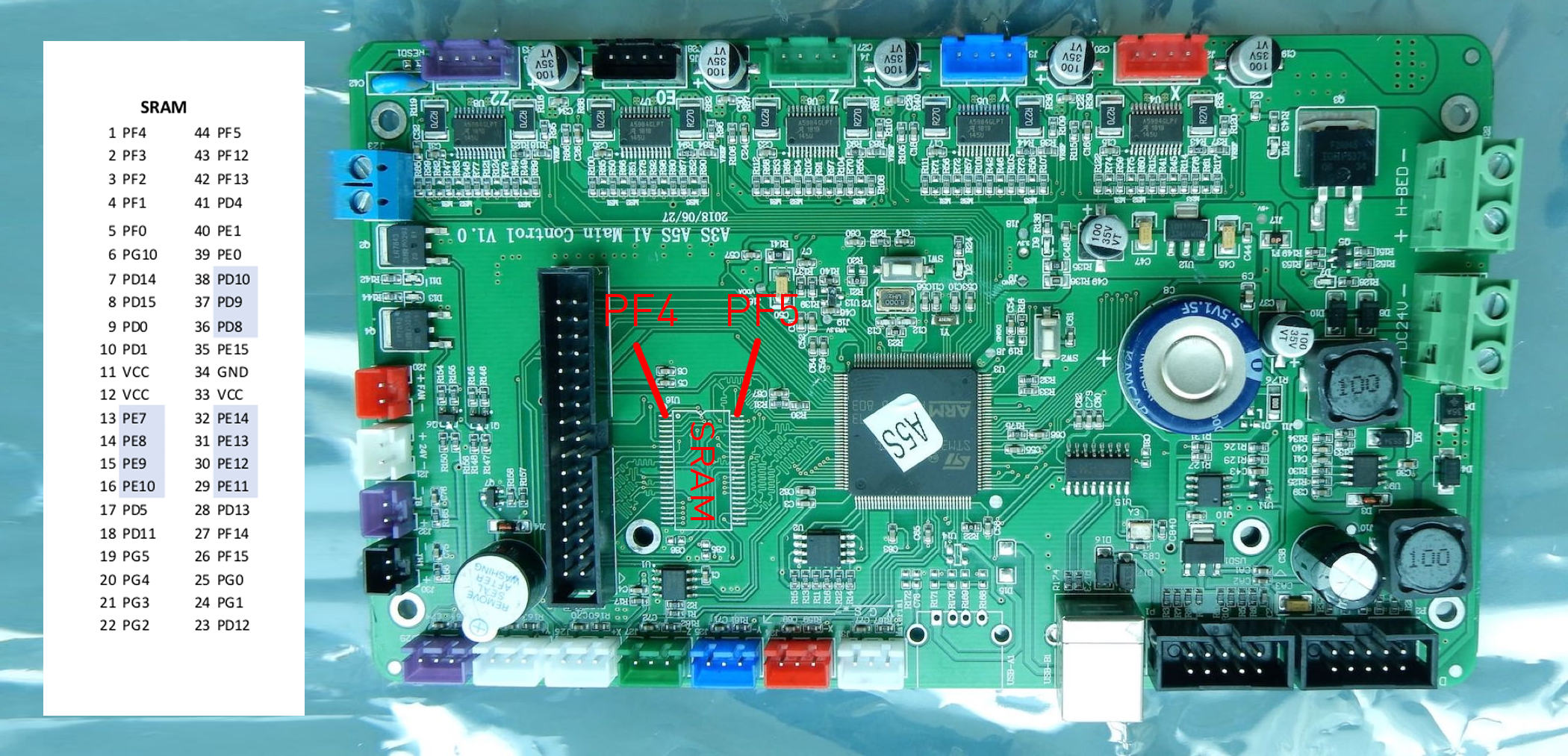
Since using the endstop pins on the controlboard from JGAurora is problematic we will solder two wires to the SRAM pins exposed next to the lcd header.

PF4 will be our Signal wire, PF5 our Endstop/Sensor wire.
Wireing the BLTouch is visualized below:

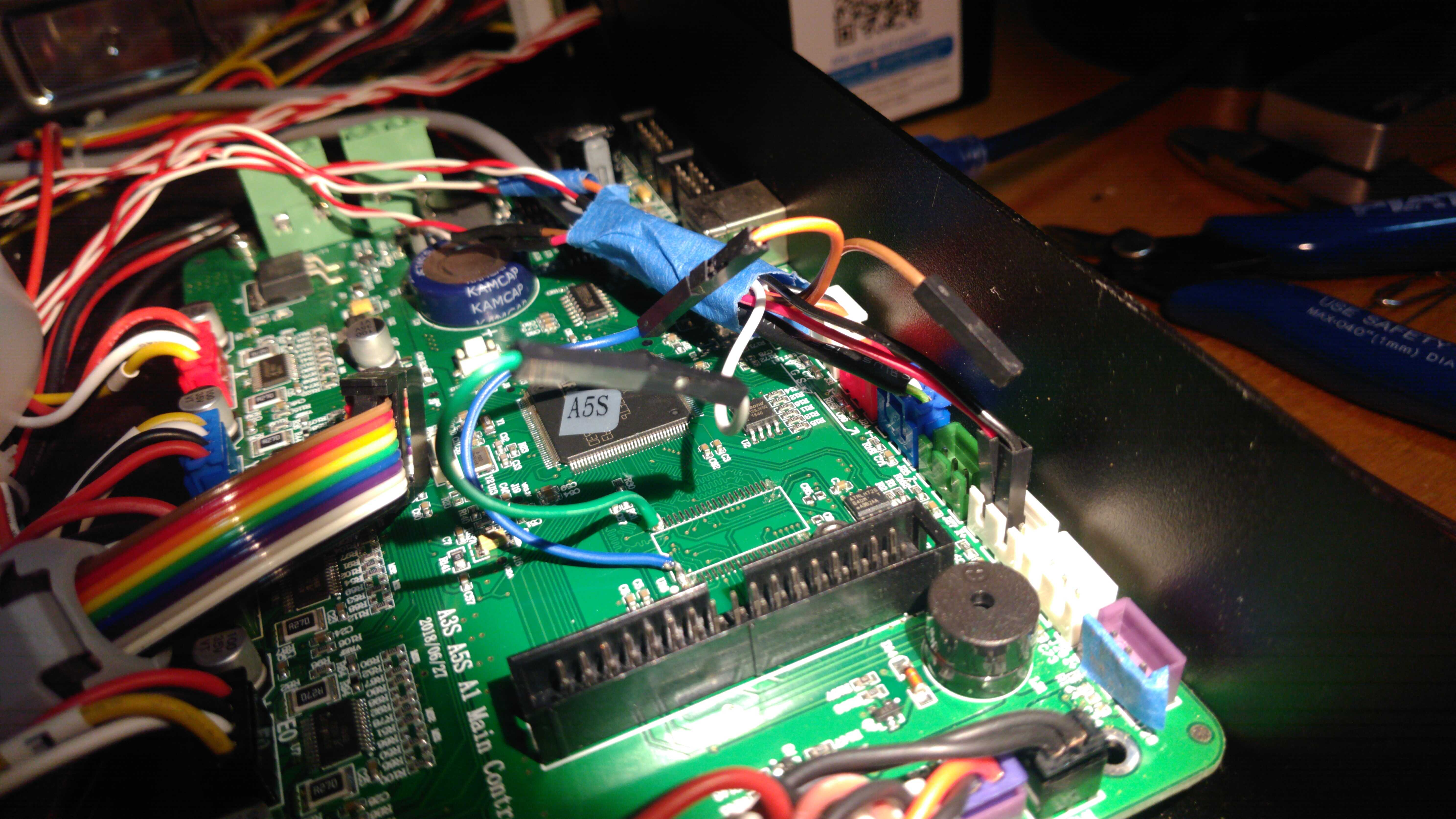
This is how it looks in my case:

I secured some of the cables to the board with some tape afterwards.
You might want to test the functionality carefully before closing up the case again.
You can route the wire through either the hole in the case under the lcd in the front or the back at the power supply. Alternatively I drilled a hole right at the vertical frame.
Once the wiring is set up you can flash my modified Firmware. Besides adding BLTouch support and Unified Bed Leveling there are other small tweaks and changes.
You might have to immediatly autotune the PID values for the heated bed by sending a "M303 E-1 S60 C8 U1" to prevent thermal runaways. Don't forget to tune the hotend PID values later too.
Then get an initial value for the z-Probe offset: http://https//www.youtube.com/watch?v=y_1Kg45APko
This will probably not give you a perfect first layer. You will be able to adjust the offset while printing the first layer just like babystepping. It wont be automatically saved to eeprom though.
For a detailed guide to Unified Bed Leveling see this video: http://https//www.youtube.com/watch?v=ONpKxkil16Q
or look at this guide: http://http//marlinfw.org/docs/features/unified_bed_leveling.html
It should be possible to do all this from the LCD but I didn't bother to look into it.
This is my starting Gcode adapted from the original slicer guide from the wiki:
;M190 S60 ; Heat up the print bed and wait, probably not needed
G28 ; Home all axis
G29 L1 ; Load mesh bed level
G29 J3 ; Check/Update bed level
G1 X0.0 Y0.0 F1000.0
;M109 S200 ; Heat up the hot end and wait, probably not needed

G90
G1 Z15.0 F6000 ; Move up 15mm at 6000mm/min (note: more than the max speed set in the printer firmware)
G92 E0 ; Reset extruder length to zero
G1 X0.0 Y0.0 F1000.0 ; go to edge of print area
G1 Z0.200 F1000.0 ; Go to Start Z position
G1 X60.0 E9.0 F1000.0 ; intro line
G1 X100.0 E21.5 F1000.0 ; intro line
G92 E0.0 ; reset extruder distance position
I hope this will make using a BLTouch possible for the people who crave ABL. It enabled me to start prints with perfect and consistent first layers every time.
And most importantly, thanks to Samuel for his amazing work on the printer and the firmware. He is the one who made this possible!
PS!!!! Please tell me immediatly if there is something wrong with the firmware!!!! Since I modified more then just the BLTouch on my printer I can't test this specific build!!!!
Post edited by Frezap on
Comments
#define BABYSTEP_ZPROBE_GFX_OVERLAY
#define Z_STOP_PIN PF5
#define NUM_SERVOS 1
#define SERVO0_TIMER_NUM 8
https://thingiverse.com/thing:3887227
I changed my board out with a Bigtreetech SKR v1.3 32bit board to use the BLTouch. It is a little quieter with TMC 2208 stepper drivers, but I will be changing back to the stock board so I can use the stock LCD. The new board will go to my Anet Core A8 conversion.
Thanks again!!
I'm kind of new to the 3D-printing modifications
So my question is:
If I change the mainboard with a newer one that supports auto-leveling! will I need to modify the firmware, I mean that what I already installed in my printer which is Marlin 2.D.
cheer!
The reason is that the factory firmware SD bootloader/flasher does not flash the entire firmware, it only flashes the bin file to the region after the SD bootloader. To make this work, you need to change the compiler to link based on a different entry address. Please take some time to view the linker files for the Marlin firmware for the A5S. If you want to flash the entire firmware area, you need to use an ST-Link device.
I have fallowed this tutorial to add bltouch (antclabs) to my a5s. I did everything correctly but I'm getting stuck on making the firmware for the printer. Every time I compile with vscode the file size is 8kb and when I flash it to the printer it won't boot. Would anyone know where I can get all the files to make the proper firmware?
Thanks in advance.
I have been trying for days to get this working with Marlin 2.07 firmware just not got what it takes anyone got a copy of both configuration h and configuration advh to send me i know i will need to alter my probe position but hopfully that may work.
Thanks
So, looking at the annotated photo, I think the 3.3 volts is actually 5 volts (which is what the BLTouch needs to deploy/stow the probe)... at least that's what I'm seeing on my multimeter...
Does anyone have any of the images that were in this post? Especially the wiring for the A5S w/ v1.1 board?
I cant seem to find anything clear that shows the wiring and the images in this post no longer work for me
Thanks for letting me know .. the old jgmakerforum domain was snagged and I was still linking to it ... pictures will be back momentarily....
Much appreciated @Samuel Pinches
Looking forward to the enhanced images, see what kind of trouble I can get into this weekend
Fixed
Thank you!
Howdy, Stranger!
RegisterIt looks like you've been lurking for a while.
If you register, we will remember what you have read and notify you about new comments. You will also be able to participate in discussions.
So if you'd like to get involved, register for an account, it'll only take you a minute!