Please note: the forum is closed.
No new user registrations are accepted. For more info, please click here.
No new user registrations are accepted. For more info, please click here.
Convert (adapter) PCB on A5S
Recently I had trouble with mainboard on A5S and now I am looking for what caused the damage.

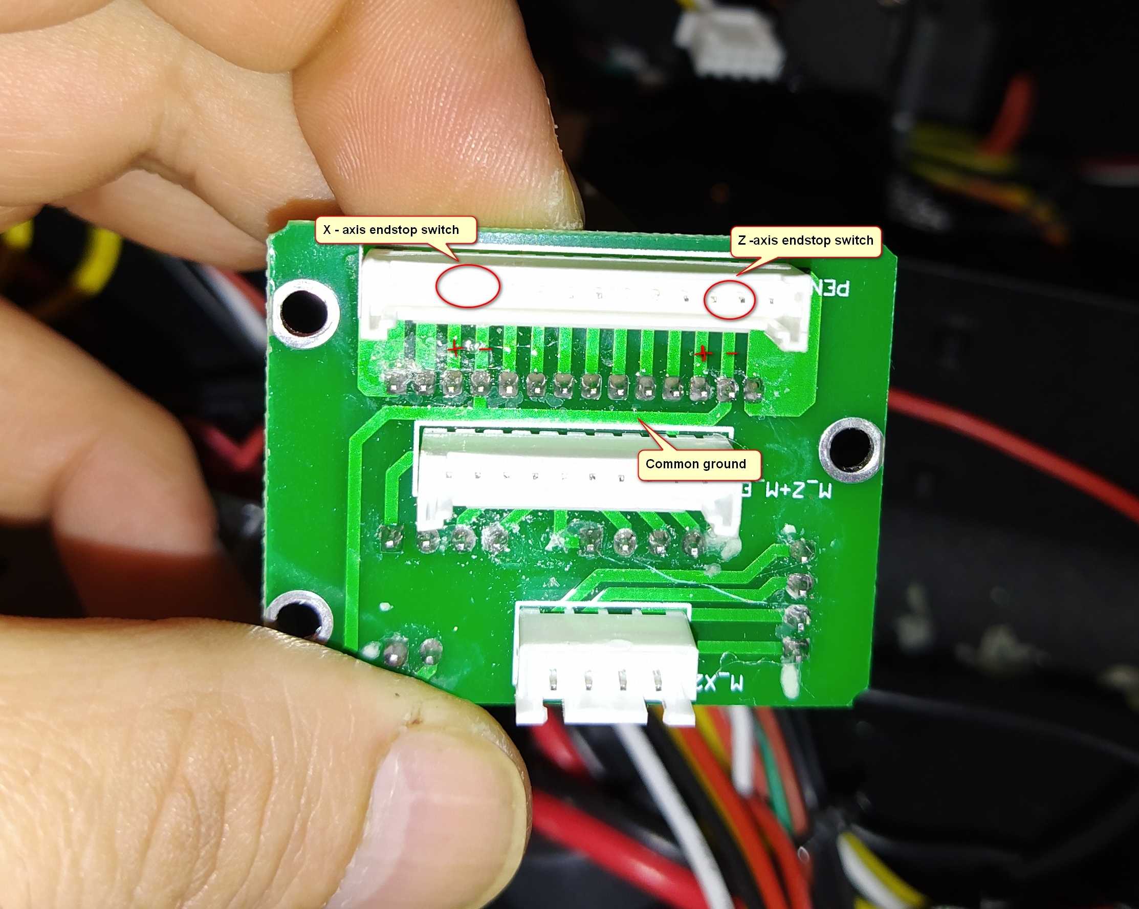
X-axis endstop slot on original board does not react any more on signals, it is locked in NC position. Rest of hardware on printer is ok.
After
playing around with Lerdge X and few small succesufull prints, same
problems started on Lerdge like with original board before it had
damage.
After deep inspection of everything, only possible and logical cause of problems can be Convert PCB.
As picture shows, x and z axis endswitch have common ground and that is in certain scenarios cause for printers strange behavior.
And
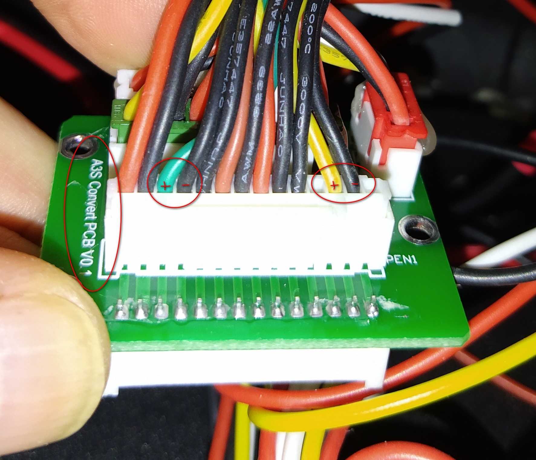
on PCB is written A3s Convert board, I am not sure is it design /hw
borrowed from previus A5 or it is mistake in factory assembling?
Your opinion guys?


Comments
As I said previously, the standard procedure is to re-flow with 60/40 solder - you can do it quickly and easily with a soldering iron and liquid flux - then clean up the PCB with isopropyl alchohol and cotton buds
Lead free solder is the worst thing ever invented for electronics assembly
But think for a second: when x endstop switch let the signal (+) through common ground to the mainboard, automatically z slot on mainboard gets signal too.
So i.e. when x is homed, mainboard "thinks" z is homed too.
They are divided sections on main board with divided + and - lines, common ground between endstops and mainboard does not fit at all.
Here is video what is goin on, everything is connected as original :
https://drive.google.com/file/d/1KUheFth8fcn1HMHDzjediqGRHiyf8PIO/view?usp=drivesdk
If you are convinced the problem is shared ground - simply cut the track with a utility knife and make two direct wire connections to the metalwork of the controller case from the PCB tracks
Anyway, we are only changing logic 1 to logic 0 on the controller sensing pins
Also, how many of the controller board sockets are common ground?
Your scheme is correct.
Have you measured a voltage drop on the + side of the open switch with a voltmeter when you close the other switch manually?
Edit: If both those + voltages originate from the same source, and has insufficient current, one switch closing to ground could pull the + voltage for the other down as well, which could then be below the logic 0 threshold, and flip the logic state of the input pin
The electronics department will be able to test for "noise" and "pulses" which could be making the board unstable
Howdy, Stranger!
RegisterIt looks like you've been lurking for a while.
If you register, we will remember what you have read and notify you about new comments. You will also be able to participate in discussions.
So if you'd like to get involved, register for an account, it'll only take you a minute!