Please note: the forum is closed.
No new user registrations are accepted. For more info, please click here.
No new user registrations are accepted. For more info, please click here.
A5 - and what became out of it...
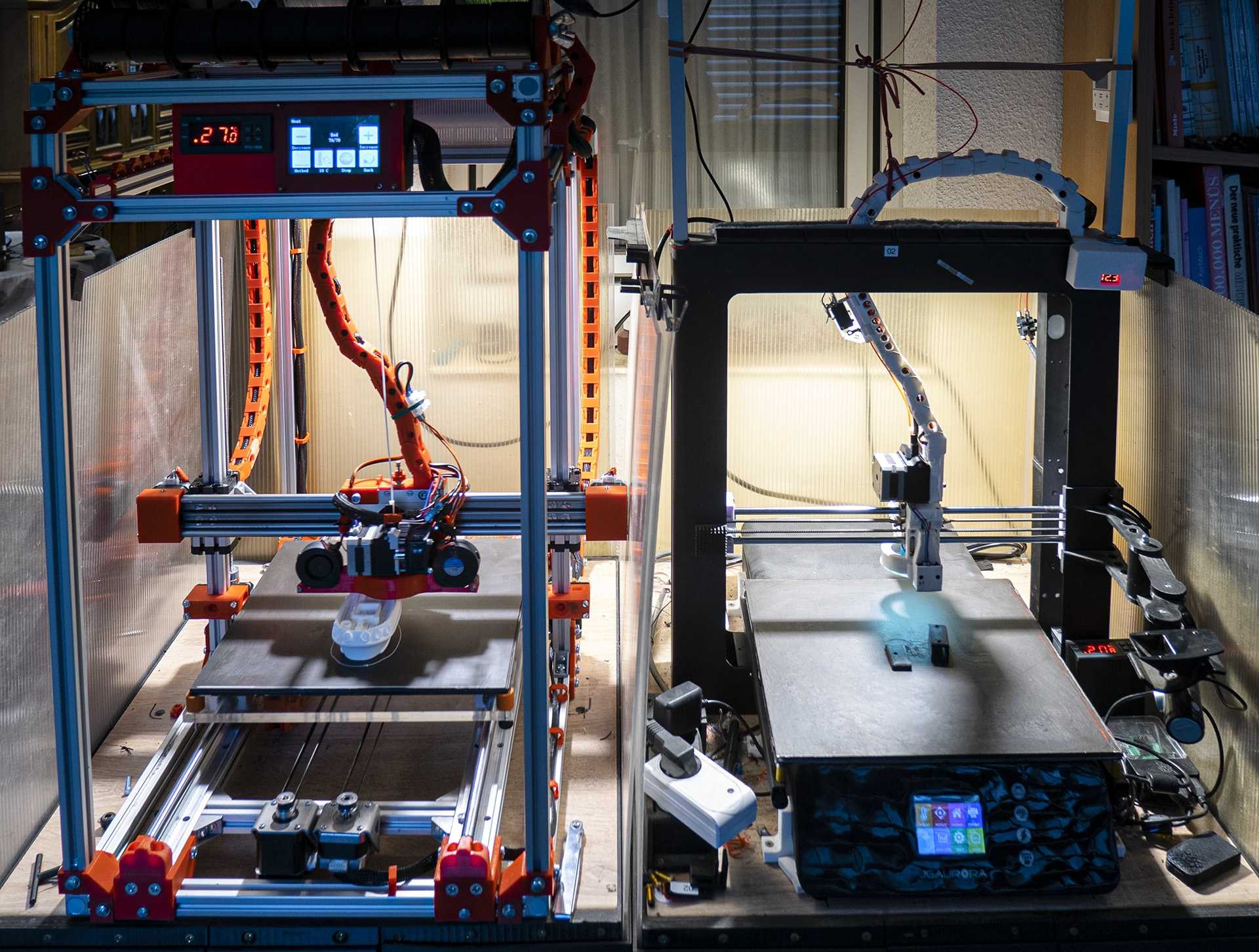
How to get perfect prints out of your A5? Quite easy. Take two of them, place them side by side and start building a new printer in front of them whilst both of them do know the rumors that there might be some need that one is to be disassembled ... Never had them causing that less trouble as when printing the parts for the new one ;-)
OK, but here´s the full story. After installing SKR 1.3 board I had to face the fact that all the attempts to stiffen the A5 rag to keep up with the new printing speeds were missing the mark. Gantry and Z-Axis could not be stiffened neither in the old metal, nor the newer plastic guidance version. Both had the nozzle bouncing far far beyond what could ensure a perfect print. Against my expectations the newer plastic version has made the race and the older metal versions had to contribute some parts. Especially the strong and well build power supply from the A5, the heatbed and lots of parts from earlier modifications made their way to the new one. unfortunately the LED Panel broke on the way - if you ever tear it out of the housing make sure that the touch panel doesn´t stick to the front foil much better than to the LED Panel itself...
For stiffness was on top of the list the two column one arc construction of the A5 was no option. On most of the 4 Column Case construction I didn´t like the small 8mm guiding rods. A5 had proven that they bend in each and every direction. Really higher dimensions would have been hard to be integrated in that standard 4 column cases. I found my solution with igus drylin Q plain bearings that use standard 20x20mm alu profile as guide rail. So the guide rail can be just one of the profiles of the housing.
The drylin Q modules can be adjusted in 3 directions and will give a perfect and wiggle free glide if once adjusted. But that´s what I had to learn - what they don´t like at all is two really strong motors on each side of Z axis that by accident work in opposite directions... The gliding elements got jammed this way and I had to open the topcase of the module, search quite a while for the metal balls and strong springs that got shot over the working place and - after loosening the gliding elements - bring it all together again.
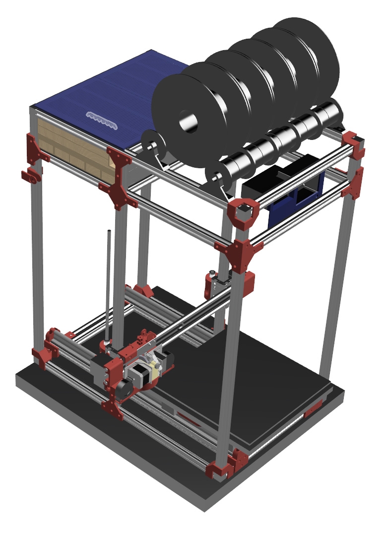
To make the construction clearer , here´s some sketch of the new printer.
My experiences with the Z Axis motors of the A5 where, that even after changing my rods to more precise T2 rods -
all you might need to know about T2 rods is nicely presented here:https://www.youtube.com/watch?v=b9qfP6Dqjxkhttp:// -
and anti backslash nuts I didn´t get the continuous precision I wanted. First exchanging the original Z Axis motors on one of the A5 with the much stronger Extruder Motors that got redundant changing the extruder on both A5 I got a reliable height layering. So I made my choice for Z Axis of the new printer on 17HS8401 (2Amp, 1,8 Ohm, 52N,c holding torque). Even powered both in parallel with a single TMC2208 driver (1,4A for both) they could lift a test load of 8KG without any stepping loss and without any noticeable heat emission. To heat em up just a little - I´ve switched to TMC5160. 3 Amp for both is more than enough and will em bring up to about 60°. I didn´t dare to have my finger in their way any more...
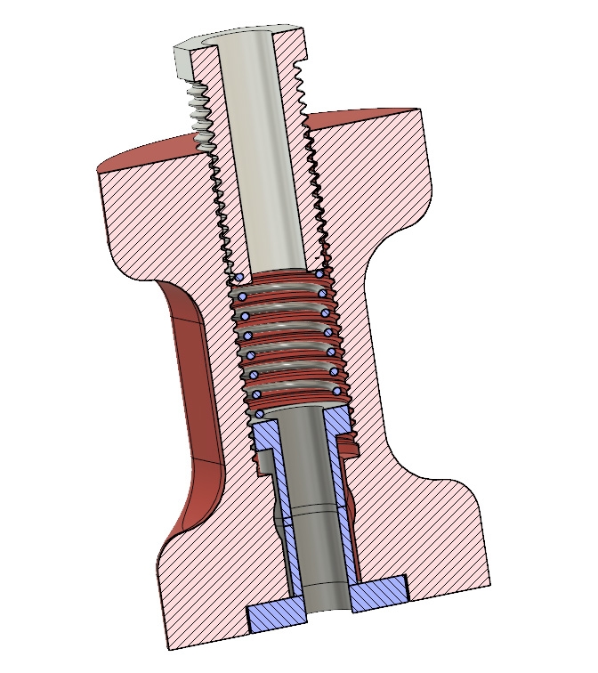
A5 allows a printing height of 320 mm out of the 400 mm rods. Backslash Nuts normally do cost 20 mm printing height for they have two bolts and a spring that reduce the play in the thread. To avoid this - and even get more printing height out of the rods, I mounted the nuts upside down. Therefore I needed to replace the spring from between those two nut elements on top of them. The pic shows the construction of the housing driver for the drylin Q bearings that too is the housing for the modified anti backslash nut. 3d printed hollow screw compresses the spring and gives room for the rod to glide through. The two nut parts and the spring of the backslash assembly show blue, the housing and the hollow pressure screw are in red.
In real live it looks like this:
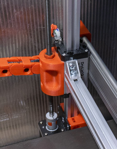
For the rod only needs to dive 20mm into the housing to be hold by both of the nut parts, the usable printing height now is 355 mm. I´ve missed the intended 375 mm cause I found that I can´t align the motor precise enough underneath the rod so I can drive the housing straight onto the motor coupler. The coupler itself has some play to smooth out small deviations from motor and rod axis. Therefore every now and then driving the z axis to deep it missaligns to the motor on the opposite side of the Z axis. Giving 20 mm Room between motorcuopler and nuts helps to stay away from this missaligning.
For the Z-Axis gantry I´ve choosen igus WWE-10-40-20 slider on WS-10-40 rail. I wanted to avoid two separate guiding pipes that needs to be aligned against each other. WS-10-40 has two Pipes, that are connected on a torsion-resistant bed. First I´ve planned to drill away as much of the bed as possible to reduce the weight - but finding I how powerfull the two 17HS8401 motors are, I´ve skipped this and benefit from the additional stiffness. The WS-10-40 rail is fixed with 4 Screws on each side onto the drylin Q bearings.
From the front it looks like this:
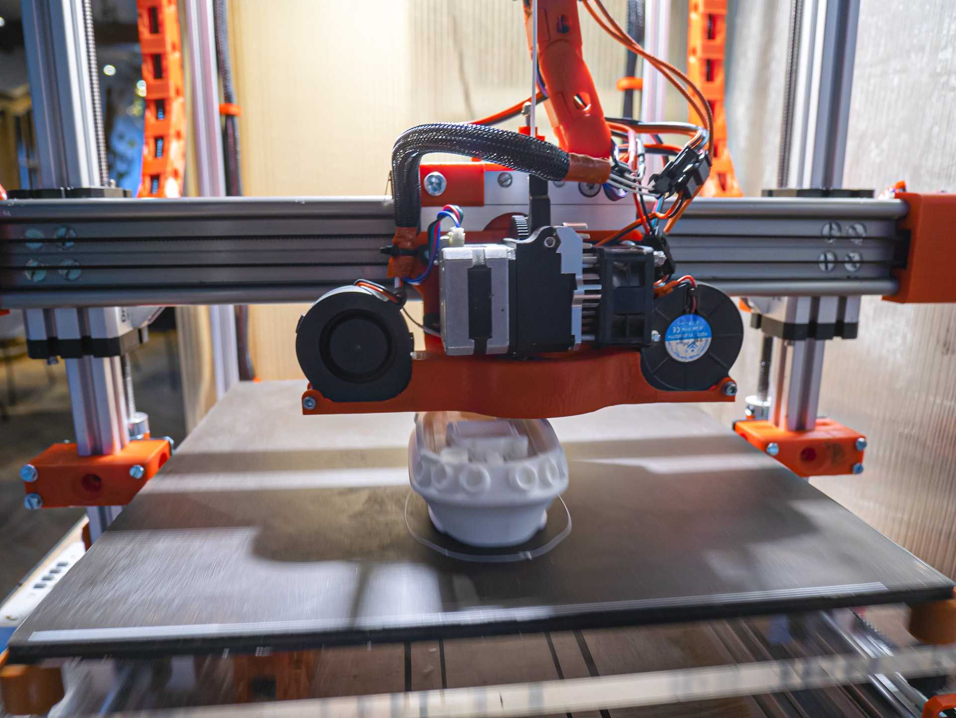
The WS-10-40 Rail is perfectly suited to house the GT2 Belts for the Extruder Slider. I´ve attached the Nema 17 Motors directly on the back of the Rails - what wasn´t the best idea. The screws of the motors interfear with the two pipes on the rail, so it´s quite hard to drill them straight through that uneven structure. Next time I´d add some holders to the end of the rail.
As shown the rail overhangs the wide of the printer housing. This gives plenty of room for two extruder carriages for example - OK therefore the fans should be assembled a little bit more tight. But I´ll use this version for speed primarily and - that´s the greatest advantage of the WWE-10-40-20 slider on that rail - loosening 4 screws will give you a plain aluminium plate that you can interchange quickly with different extruder mountings. I plan to prepare some plate for an engraving motor in addition ... Will see if the stiffness will stand this challenge too.
I´ve made my choice on a titan extruder mix. A mix, cause I had poor experiences with the durability of the original plastic version. So I´ve added a full metal Titan extruder housing with an Titan aero sideplate. I like this combination, cause from extruder gear to tip of volcano nozzle the way the filamend will travel is less than 30 mm and it´s one short unit that doesn´t give any room for a playing nozzle tip. Most important - even too the extruder wheel from the metal version often fails. Got rid of the problems by help of an extruder wheel like this: https://www.aliexpress.com/item/32805823457.html?spm=a2g0o.productlist.0.0.767d31a3LXy48C&algo_pvid=0bb64cae-fdb1-4d1a-b42d-6cc1c67316a3&algo_expid=0bb64cae-fdb1-4d1a-b42d-6cc1c67316a3-9&btsid=3a31ace8-179b-4cf7-a05c-2468712e999d&ws_ab_test=searchweb0_0,searchweb201602_6,searchweb201603_52 . It has sharp curved teeth to drive even flex filament without problems.
The fans by the way - ball bearing and the most silent I´ve been testing for the last years - did cause an unexpected problem. For having fans with axis in x and y direction they are building up vibrations. I had to redo the fan holder and tighten it on some more places to the aluminium ground plate of the slider.
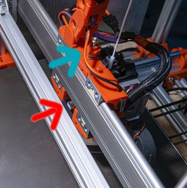
The IR Sensor for leveling the Z-Axis is on the backside of the slider (red arrow). It´s a simple case with some spring loaded guides at the sides and a long M3 threaded rod heading to the top of the slider. To set the nozzle height the sensor can be lowered or raised by help of that nuts (blue arrow).
By the way - on the picture you can see the hotbed. It´s the original of the A4 but there is an magnetic foil glued on the glas and the printint surface is a 0,8 mm metal plate that´s been painted with acrylic paint so the IR sensor can handle the surface without any errors.
From the front it looks like this - the hotbed springs had to give way for 4 silicone bumpers.
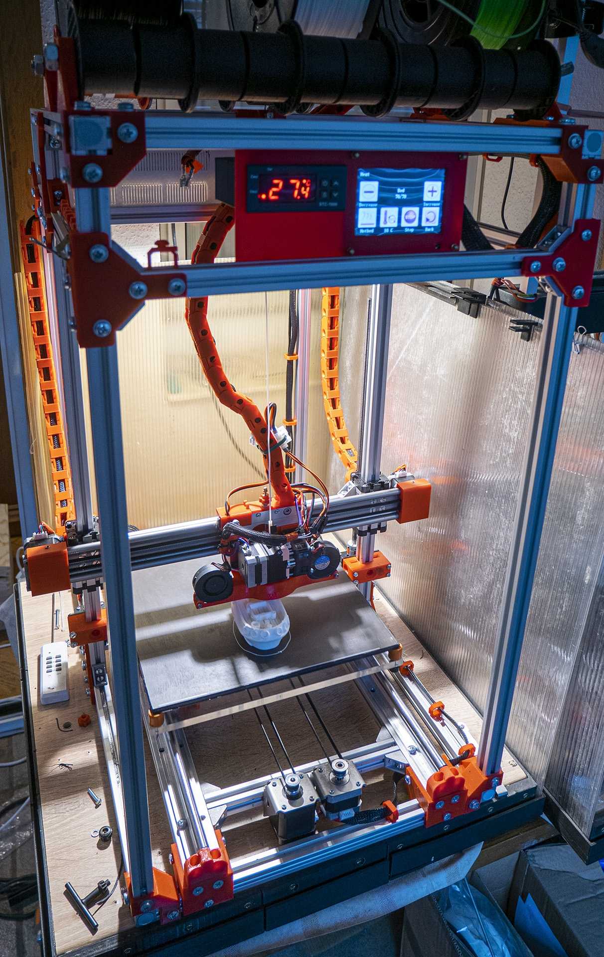
The Y sledge resides on two SBR12 Rails. After a first test with the original ball bearing blocks on SBR, they turned out to be far to loud and unprecise. So I switched to plain bearing blocks. They are smooth and precise - but do cause a lot more friction than the ball bearing ones. The problem I ran in wasn´t the power of the motor, but the weakness of the GT2 toothed belt on the long way. I solved the problem by mounting two 17HS8401 motors - one in the front and one in the rear end of the frame. Having two motors in the picture in front was just caused by having them from the old A5 and it was the perfect way to have working motor and counterbearing in same position using same holding construction. To ease it up the spare motores have geared pulleys, so they don´t waste power beeing rotated.
By the way - I didn´t find any stronger (and cheaper) nema 17 mountings like these https://www.ebay.de/itm/Schrittmotor-Halterung-Stepper-Motor-Mounting-Bracket-NEMA-17-FLEX/362621486719?hash=item546decc67f:g:IsYAAOSwqktc-26Y that do allow position adjusting in so many ways.
The bed travels about 60mm each side more than needed to get the nozzle on any position on the bed. Reason is that the IR Sensor is 40 mm behind the nozzle and on the old A5 there alway was a strip it couldn´t measure and often guessed the wrong
deviations in this area. Now nozzle as well as IR Sensor can reach any part of the bed. It was some pain to set the leveling area independently from the real bed area. There are a lot of dependencies in the firmware definitions. I first got perfect results by adding in fixed values for MESH_MIN_Y / MESH_MAX_Y in stead of formulas. There is an interesting discussion about repositioning of oversized moving spaces https://community.ultimaker.com/topic/12504-xy-start-print-offset-setting-in-cura/ - but it doesn´t cover UBL-Leveling too. So if anybody has an idea for a clever setup I´d be pleased to hear.
The electronics made their way into a housing that covers the topmost back of the rag:
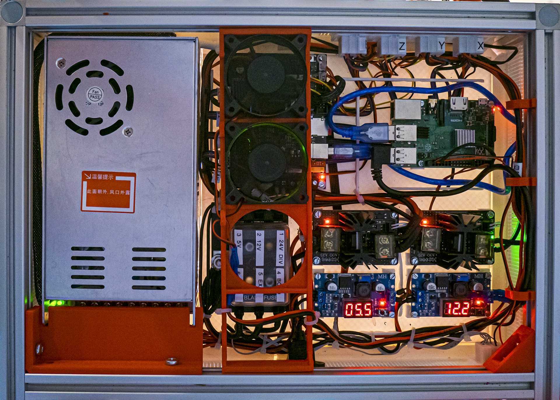
Since I use an SKR 1.3 board the big mosfeds for extruder and bed are not essential any more, but help to separate the board from any shortening in that lines. In addition all instances are separated by help of a small fuse block taken from car equipment. The raspberry and some additional 12V modules are powered by step down modules. A big issue is the power down peak. I need to implement some freewheeling diode to protect the electronics.
The change form TMC2208 in UART mode to TMC5160 in SPI mode ain´t a big deal - after you´ve reviewed this video, that explains anything to know - even some workaround for "first series" TMC5160 issues that in my 1.2 version chips are still alive: https://www.youtube.com/watch?v=dOJbSrWVu_Q
There´s only one issue I´m still dealing with. Changing from stealthChop to spreadCycles on TMC2208 was painless. On TMC 5160
during wide speed jumps that change can cause skipping. At the moment I´m driving YX in steathChop and ZE in spreadCycles avoiding any skips. After running a couple of test prints with 100mm sec for everything beyond the 4th layer, I´m now running 200mm/sec prints - till now with good quality and without any skips. Will see how far we can speed up...
The pin for sensorless homing is soldered - but I didn´t find the time to figure out if it will work with highest speed movements. So it´s still deactivated.
So it´s now one and a somewhat half or quarter A5 - and I primordially bought an A5 not to become a modder ;-)
Comments
Howdy, Stranger!
RegisterIt looks like you've been lurking for a while.
If you register, we will remember what you have read and notify you about new comments. You will also be able to participate in discussions.
So if you'd like to get involved, register for an account, it'll only take you a minute!